A system and method for in-situ continuous neutralization of acid tailings leachate

A leachate and acidic technology, applied in the field of soil pollution treatment, can solve the problems of uncontrolled soil acidification in the lower layer, heavy metal pollution in groundwater acidification, and difficulty in determining the amount of alkaline mixture, etc., to achieve stable treatment effect and cost The effect of low and high mechanical strength

Active Publication Date: 2020-12-22
KUNMING UNIV OF SCI & TECH
View PDF19 Cites 0 Cited by
  • Summary
  • Abstract
  • Description
  • Claims
  • Application Information

AI Technical Summary

Problems solved by technology

Currently, the commonly used treatment methods mainly include land reclamation, ex-situ treatment, or use of tailings to develop building materials, but these methods are not effective in preventing and controlling the leachate problem of acid tailings field and water pollution, and the cost of ex-situ treatment is high. Therefore, it is imperative to find an efficient and low-cost in-situ treatment method
[0008] At present, to deal with the problem of acidic leachate in acidic tailings ponds, it is mainly to lay neutralization slag or artificial soil, or to use alkaline substances and acidic mine soil to mix and plow, and then plant vegetation for treatment, such as a strong Ecological restoration method of acid tailings pond (CN107347402A), a method for restoring vegetation without covering soil in strong acid tailings pond (CN104624620B), a formula of nutrient-type tobacco field soil acidification improver and its use method (CN104893733A), However, these methods are not easy to determine the amount of alkaline mixture, and can only temporarily control the acidification of the surface tailings soil, but cannot control the acidification of the underlying soil for a long time, and cannot solve the acidification of groundwater and heavy metal pollution.

Method used


Image

  • A system and method for in-situ continuous neutralization of acid tailings leachate
  • A system and method for in-situ continuous neutralization of acid tailings leachate
  • A system and method for in-situ continuous neutralization of acid tailings leachate

Examples


Embodiment 1

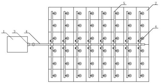
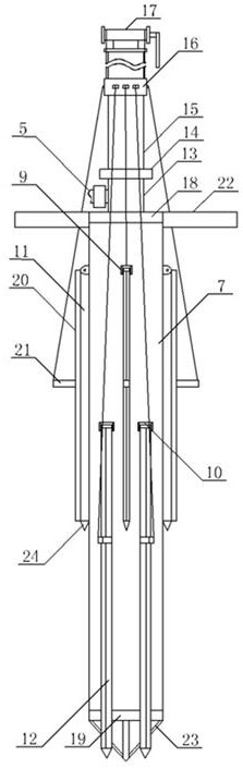
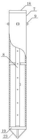
[0039] Such as Figures 1 to 4 As shown, the system for in-situ continuous neutralization of acid tailings leachate includes a liquid storage tank 1, a pipeline system and an alkaline treatment liquid irrigation device; the pipeline system includes a main valve 3, a main pipeline 4, a branch pipeline 5 and Branch valve 6, the alkaline treatment liquid watering device includes casing 7, watering pipe 8, first hinged seat 9, second hinged seat 10, first movable frame 11, second movable frame 12, liquid supply chamber 13, Pedestal 14, sliding column 15, sliding sleeve 16, rope winding device 17, upper end cover 18, lower end cover 19, cone platform 20, rope connection position 21, foot pedal 22, cone-shaped soil breaking frame 23 and cone-shaped soil breaking head 24 ;

[0040] Described reservoir 1 is connected main pipeline 4 by pump, and main pipeline 4 is provided with some branch pipelines 5, and each branch pipeline 5 pipelines connects each alkaline treatment liquid water...

Embodiment 2

[0048] Such as Figures 1 to 4 As shown, the system for in-situ continuous neutralization of acid tailings leachate includes a liquid storage tank 1, a pipeline system and an alkaline treatment liquid irrigation device; the pipeline system includes a main valve 3, a main pipeline 4, a branch pipeline 5 and Branch valve 6, the alkaline treatment liquid watering device includes casing 7, watering pipe 8, first hinged seat 9, second hinged seat 10, first movable frame 11, second movable frame 12, liquid supply chamber 13, Pedestal 14, sliding column 15, sliding sleeve 16, rope winding device 17, upper end cover 18, lower end cover 19, cone platform 20, rope connection position 21, foot pedal 22, cone-shaped soil breaking frame 23 and cone-shaped soil breaking head 24 ;

[0049] Described reservoir 1 is connected main pipeline 4 by pump, and main pipeline 4 is provided with some branch pipelines 5, and each branch pipeline 5 pipelines connects each alkaline treatment liquid water...

Embodiment 3

[0057] Such as Figures 1 to 4 As shown, the system for in-situ continuous neutralization of acid tailings leachate includes a liquid storage tank 1, a pipeline system and an alkaline treatment liquid irrigation device; the pipeline system includes a main valve 3, a main pipeline 4, a branch pipeline 5 and Branch valve 6, the alkaline treatment liquid watering device includes casing 7, watering pipe 8, first hinged seat 9, second hinged seat 10, first movable frame 11, second movable frame 12, liquid supply chamber 13, Pedestal 14, sliding column 15, sliding sleeve 16, rope winding device 17, upper end cover 18, lower end cover 19, cone platform 20, rope connection position 21, foot pedal 22, cone-shaped soil breaking frame 23 and cone-shaped soil breaking head 24 ;

[0058] Described reservoir 1 is connected main pipeline 4 by pump, and main pipeline 4 is provided with some branch pipelines 5, and each branch pipeline 5 pipelines connects each alkaline treatment liquid water...


PUM


Abstract

The invention relates to a system and method for in-situ continuous neutralization of acid tailings leachate, belonging to the technical field of soil pollution treatment. The system for in-situ continuous neutralization of acid tailings leachate includes a liquid storage tank, a pipeline system and an alkaline treatment liquid irrigation device; the pipeline system includes a main valve, a main pipeline, a branch pipeline and a branch valve, and the alkaline The treatment liquid pouring device includes a casing, a pouring pipe, a first hinged seat, a second hinged seat, a first movable frame, a second movable frame, a liquid supply chamber, a pedestal, a sliding column, a sliding sleeve, a rope winding device, and an upper end cover , lower end cover, cone platform, rope connection position, pedals, cone-shaped soil breaking frame and cone-shaped soil breaking head. The system of the present invention only needs to irrigate and bury the alkaline treatment liquid into the soil plot and connect it to the pipeline system to continuously treat the acid tailings pond, and has the advantages of continuous stability, good treatment effect and convenient operation.

Description

technical field [0001] The invention relates to a system and method for in-situ continuous neutralization of acid tailings leachate, belonging to the technical field of soil pollution treatment. [0002] technical background [0003] Acidic leachate is the continuous reaction between sulfur-containing tailings and oxygen in the air, and sulfuric acid is formed under the action of rainwater, which makes the pH of tailings leachate acidic (pH=2-4): [0004] . [0005] At the same time, the acidic leachate will dissolve other associated metals in the tailings, such as Cu, Mn, Cr, Pb, etc., causing pollution to the downstream environment. The use of alkaline solution to treat tailings not only has the effect of neutralizing acidic leachate, but also can react with acid-leached metal ions to form precipitates, reducing heavy metal pollution. The reaction mechanism is: [0006] [0007] Mine tailings have always been one of the most difficult problems to deal with, and they...

Claims


Application Information

Patent Timeline
Patent Type & Authority Patents(China)
IPC IPC(8): B09C1/00
CPCB09C1/002B09C2101/00
Inventor 黄建洪陈允建田森林胡学伟李英杰
Owner KUNMING UNIV OF SCI & TECH
Why Eureka
Try Eureka