
Novel method for preparing artificial stress corrosion crack by utilizing photoetching and powder metallurgy technology

A stress corrosion cracking and powder metallurgy technology is applied in the field of preparation of stress corrosion cracking simulation specimens, which can solve the problems of difficult preparation of artificial stress corrosion cracking specimens, unknown electrical conductivity in cracked crack areas, etc., and achieves easy realization and low processing cost. , the effect of simple operation

Inactive Publication Date: 2019-04-12
XI AN JIAOTONG UNIV
View PDF4 Cites 1 Cited by
  • Summary
  • Abstract
  • Description
  • Claims
  • Application Information

AI Technical Summary

Problems solved by technology

[0004] In order to solve the above-mentioned existing artificial stress corrosion crack test piece preparation difficulties, the size of the prepared crack and the electrical conductivity of the crack area are unknown, the object of the present invention is to provide a method for preparing artificial stress corrosion cracks using photolithography and powder metallurgy technology. The new method can prepare stress corrosion cracks with known crack size and electrical conductivity. This method has the advantages of simple operation, easy implementation, and low cost. The prepared stress corrosion crack size and electrical conductivity are known. It can be widely used in stress corrosion cracks. Corrosion crack quantitative non-destructive testing capability certification system

Method used


Image

  • Novel method for preparing artificial stress corrosion crack by utilizing photoetching and powder metallurgy technology
  • Novel method for preparing artificial stress corrosion crack by utilizing photoetching and powder metallurgy technology
  • Novel method for preparing artificial stress corrosion crack by utilizing photoetching and powder metallurgy technology

Examples


Embodiment 1

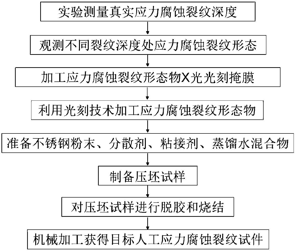
[0033] In this embodiment, a new method for preparing artificial stress corrosion cracks using photolithography and powder metallurgy technology includes the following steps:

[0034] Step 1: Processing of stress corrosion crack morphology based on photolithography and electroplating technology, the specific steps are as follows:

[0035] 1) For example figure 2 For the real stress corrosion crack test piece shown, the depth of the real stress corrosion crack is measured by TOFD ultrasonic testing equipment;

[0036] 2) Observe the morphology of surface stress corrosion cracks through a microscope to obtain the surface crack morphology diagram of the real stress corrosion cracked specimen;

[0037] 3) On the transparent film, print the surface crack morphology diagram of the real stress corrosion cracked specimen obtained in step 2), such as image 3 As shown, a carbon plate is selected as the substrate, a thin layer of photoresist is laid on the carbon plate substrate, and...

Embodiment 2

[0047] In this embodiment, a new method for preparing artificial stress corrosion cracks using photolithography and powder metallurgy technology includes the following steps:

[0048] Step 1: a new method for preparing artificial stress corrosion cracks by photolithography and powder metallurgy technology, characterized in that: comprising the following steps:

[0049] Step 1: Processing of stress corrosion crack morphology based on photolithography and electroplating technology, the specific steps are as follows:

[0050] 1) For example figure 2 For the real stress corrosion crack test piece shown, the depth of the real stress corrosion crack is measured by TOFD ultrasonic testing equipment;

[0051] 2) Observe the morphology of surface stress corrosion cracks through a microscope to obtain the surface crack morphology diagram of the real stress corrosion cracked specimen;

[0052] 3) On the transparent film, print the surface crack morphology diagram of the real stress co...

Embodiment 3

[0062] In this embodiment, a new method for preparing artificial stress corrosion cracks using photolithography and powder metallurgy technology includes the following steps:

[0063] Step 1: Processing of stress corrosion crack morphology based on photolithography and electroplating technology, the specific steps are as follows:

[0064] 1) For example figure 2 For the real stress corrosion crack test piece shown, the depth of the real stress corrosion crack is measured by TOFD ultrasonic testing equipment;

[0065] 2) Observe the morphology of surface stress corrosion cracks through a microscope to obtain the surface crack morphology diagram of the real stress corrosion cracked specimen;

[0066] 3) On the transparent film, print the surface crack morphology diagram of the real stress corrosion cracked specimen obtained in step 2), such as image 3 As shown, a carbon plate is selected as the substrate, a thin layer of photoresist is laid on the carbon plate substrate, and...


PUM

PropertyMeasurementUnit
thicknessaaaaaaaaaa

Abstract

The invention relates to a novel method for preparing an artificial stress corrosion crack by utilizing a photoetching and powder metallurgy technology. The novel method for preparing the artificial stress corrosion crack by utilizing the photoetching and powder metallurgy technology comprises the steps of firstly acquiring geometric shapes at different depth parts of a true stress corrosion crack, adopting the photoetching technology for processing stress corrosion crack shape objects at the different crack depth parts, and adhering the stress corrosion crack shape objects so as to form a whole stress corrosion crack shape object; then putting the stress corrosion crack shape object and prepared stainless steel metal powder, dispersing agent, distilled water and an adhesive mixture into acontainer, and forming a compact specimen; and finally placing the compact specimen in a vacuum furnace, degumming and sintering, machining the sintered specimen, and obtaining an artificial stress corrosion crack specimen with the final target size and surface cracks. The specimen prepared through the method provided by the invention can artificially copy a natural stress corrosion crack in an actual structure, has the advantages of complicated crack shape and capabilities of being known and being prepared on a large scale, and can be widely applied to a detectability certification system ofa stress corrosion crack quantitative nondestructive detecting method.

Description

technical field [0001] The invention relates to the field of preparation of stress corrosion crack simulation test pieces, in particular to a new method for preparing artificial stress corrosion cracks by using photolithography and powder metallurgy techniques. Background technique [0002] Austenitic stainless steel materials sensitive to stress corrosion are widely used in nuclear power plants, and the existence of tensile stress and corrosive environment in nuclear power structures makes stress corrosion cracks widely exist in key parts of nuclear power plants, such as internal components of reactor cores, steam generators The heat exchange tube sheet expansion part, etc. The existence of stress corrosion cracks poses a huge threat to the safe operation of nuclear power structures, and considering economic benefits, it is necessary to evaluate the size of cracks, so the quantitative nondestructive testing of stress corrosion cracks is extremely important. At present, the...

Claims


Application Information

Patent Timeline
Patent Type & Authority Applications(China)
IPC IPC(8): G01N1/28
CPCG01N1/28
Inventor 蔡文路澈鹏·钟德査陈振茂李旭东陈洪恩
Owner XI AN JIAOTONG UNIV
Learn More