
Integrated multiple waste heat coupling heating system

A heating system and waste heat technology, applied in heating systems, heat pumps, heating methods, etc., can solve problems such as discarding, achieve the effects of reducing consumption, improving economic benefits, and increasing power consumption

Inactive Publication Date: 2019-04-16
DALIAN NATIONALITIES UNIVERSITY
View PDF12 Cites 2 Cited by
  • Summary
  • Abstract
  • Description
  • Claims
  • Application Information

AI Technical Summary

Problems solved by technology

However, the low-temperature industrial waste heat represented by the float glass factory is currently being discarded for nothing, or it is discharged using additional hydropower resources. It is a pity to discard it.

Method used


Image

  • Integrated multiple waste heat coupling heating system

Examples


Embodiment 1

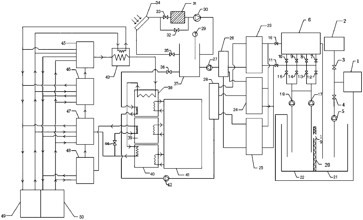
[0013] A heating system integrating multiple waste heat couplings, including a float glass waste heat recovery device, a solar waste heat recovery device and a lithium bromide heat pump heating device.

[0014] The float glass waste heat recovery device includes a float glass workshop (1), a heat pool (22), a cold pool (21), a second circulation pump (17), a two-stage control valve, a cooling tower (6), a heat pump , the first water outlet of the float glass workshop (1) is passed into the hot pool (22) by the first water pipe, the inlet of the cooling tower (6) is connected with the upper water pipe, and the outlet pipeline of the cooling tower (6) is passed into the cold pool ( 21), the upper water pipe is equipped with a two-stage control valve and a circulation pump, the upper water pipe leads to the heat pool (22), and the circulation pump is arranged at the position between the heat pool (22) and the two-stage control valve on the upper water pipe, the two-stage The valv...

Embodiment 2

[0047] A power plant waste heat, solar energy, and float glass waste heat coupling heating system. The whole system is composed of a float glass waste heat recovery device, a solar waste heat recovery device, and a lithium bromide heat pump heating device.

[0048] The main working principle of the float glass waste heat recovery device is: when the waste heat recovery is carried out in winter, the 37-39 ℃ circulating water containing a large amount of low-temperature waste heat generated by the float glass workshop 1 is discharged into the heat pool 22, and the third circulating pump 18. Pressurize the second circulation pump 17, open the eighth control valve 12, the ninth control valve 13, the tenth control valve 14, the eleventh control valve 15, and close the third control valve 7 and the fourth control valve 8 , the fifth control valve 9, the sixth control valve 10; these circulating water are introduced into the first heat pump 23, the second heat pump 24, and the third h...


PUM


Abstract

The invention discloses an integratedmultiple waste heat coupling heating system, and belongs to the field of heat supply waste heat recovery and heat distribution. The problem that a large number oflow-temperature heat sources are provided to couple heat supply with high-temperature steam provided by a power plant and a large number of low-temperature heat sources are obtained, so that low-temperature water after heat exchange continues to participate in circulation is solved.The output of the hot end of a condenser of a heat pump is a water collector, and a fourth circulating pump is installed on a front end pipeline of the water collector. The front end of the fourth circulating pump communicates with a circulating water inlet of a water storage tank of a solar waste heat recovery device, a water outlet pipe of a solar water heater is branched into two parallel water pipes, a thirteenth control valve is arranged on one water pipe and is connected with a fifth circulating pump, a fifth heat pump comprises an evaporator and a condenser, and the condenser is connected with a third output pipeline, so that the effect is that the low-temperature water after heat exchange continues to participate in circulation.

Description

technical field [0001] The invention belongs to the field of heating waste heat recovery and heat distribution, and relates to a heating system integrating multiple waste heat couplings. Background technique [0002] In recent years, with the increase of urban heating area in my country and the increase of production line construction in industrial plants, the heat consumption in my country has increased rapidly. From the analysis of heating methods, there are currently the following ways for residents to heat in my country: thermoelectricity Combined production mode, central heating of small and medium-sized regional boiler rooms, small domestic gas water heaters, household coal-fired furnaces, etc., among which the combined heat and power mode is a combination of using the high-grade thermal energy of the fuel to generate electricity and then using its low-grade thermal energy for heating Use energy technology. At present, the average power generation efficiency of a 3 mill...

Claims


Application Information

Patent Timeline
IPC IPC(8): F25B15/06F25B30/04F24D15/04F28D7/00F01K17/02
CPCF01K17/025F24D15/04F25B15/06F25B30/04F28D7/00Y02B30/625Y02E20/14
Inventor 汪语哲张皓天杨正凯李佳乐唐文宾
Owner DALIAN NATIONALITIES UNIVERSITY
Learn More