Transmitter modulation device for real-time transmission of noise measurement data
A technology of real-time transmission and noise measurement, applied in transmission systems, electrical components, etc., can solve the problems of attenuation and signal transmission susceptible to electromagnetic noise interference, and achieve the goal of avoiding interference, reducing susceptibility to electromagnetic noise interference, and improving anti-interference. Effect
- Summary
- Abstract
- Description
- Claims
- Application Information
AI Technical Summary
Problems solved by technology
Method used
Image
Examples
Embodiment 1
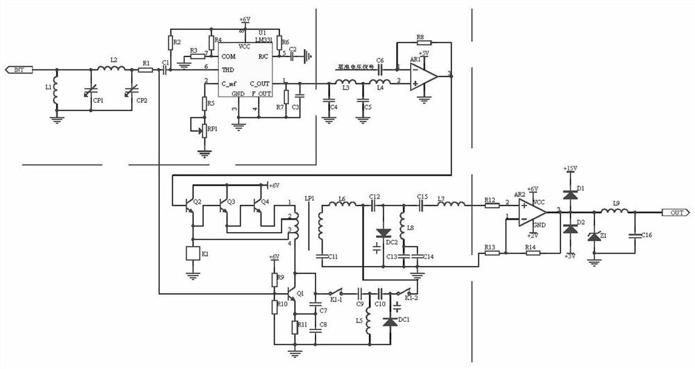
[0014] Embodiment 1, the transmitter modulation device for real-time transmission of noise measurement data, the frequency voltage conversion circuit receives the 200-1000Hz frequency signal output by the noise sensor model GSD130, and the inductance L1, the inductance L2, the variable capacitor CP1, the variable The resonant circuit composed of capacitor CP2 resonates to generate a resonant frequency to obtain a single frequency signal corresponding to the measurement noise for transmission, and then the frequency voltage is formed by the frequency voltage conversion chip U1, resistor R2-resistor R7, capacitor C1-capacitor C3, and potentiometer RP1 The converter is converted into a 2V-6V voltage signal that is linear with a single frequency signal, and then enters the frequency modulation circuit to receive the frequency signal generated by the resonant circuit, and through the impedance matching circuit composed of capacitor C4, capacitor C5, inductor L3, and inductor L4. The...
Embodiment 2
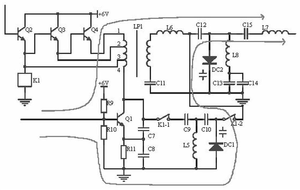
[0015] Embodiment 2, on the basis of Embodiment 1, the frequency modulation circuit receives the frequency signal generated by the resonant circuit, and obtains 2V-6V without attenuation through the impedance matching circuit composed of capacitor C4, capacitor C5, inductor L3, and inductor L4 The voltage signal, the 2V-6V voltage signal enters the subtractor of the operational amplifier AR1 as the core and subtracts the reference voltage signal corresponding to the optimal transmission frequency 900MH to obtain the frequency deviation signal. When there is no frequency deviation or the frequency deviation is less than 0.7V, the transistor Q2 Not working, the relay K1 does not act, the normally closed contacts K1-1 and K1-2 of the relay K1 do not act, the frequency signal generated by the resonant circuit passes through the transistor Q1, the varactor diode DC1, the inductor L5, and the capacitor C7-capacitor C10 as the core The 450MHz oscillating frequency generated by the LC ...
Embodiment 3
[0016]Embodiment 3, on the basis of Embodiment 2, the frequency-voltage conversion circuit receives the noise sensor model GSD130 (high measurement sensitivity: A, accurate and reliable: level 2, fast response: F, RS485 communication interface) output 200 The -1000Hz frequency signal resonates with the resonant circuit composed of inductor L1, inductor L2, variable capacitor CP1, and variable capacitor CP2 to generate a resonant frequency, so as to obtain a single frequency signal corresponding to the measurement noise and transmit it to the subsequent circuit, and then through the frequency voltage Conversion chip U1 (can be LM331), resistor R2-resistor R7, capacitor C1-capacitor C3, and potentiometer RP1 form a frequency-voltage converter to convert a 2V-6V voltage signal linear with a single frequency signal, including inductor L1 and inductor L2 , The variable capacitor CP1, the upper end of the inductor L1, the left end of the inductor L2, and the upper end of the variable...
PUM
 Abstract
Description
Claims
Application Information
 - R&D
- Intellectual Property
- Life Sciences
- Materials
- Tech Scout
- Unparalleled Data Quality
- Higher Quality Content
- 60% Fewer Hallucinations
Browse by: Latest US Patents, China's latest patents, Technical Efficacy Thesaurus, Application Domain, Technology Topic, Popular Technical Reports.
© 2025 PatSnap. All rights reserved.Legal|Privacy policy|Modern Slavery Act Transparency Statement|Sitemap|About US| Contact US: help@patsnap.com


