Blind hole uncapping method using laser

A blind hole and laser technology, which is applied in laser welding equipment, electrical components, printed circuit manufacturing, etc., can solve the problems of uneven removal of the insulating layer in the middle layer, low efficiency, and uneven thickness of the insulating layer, so as to save heating laser Increased power, processing efficiency, and reduced processing time

Active Publication Date: 2019-04-16
武汉铱科赛科技有限公司
View PDF3 Cites 5 Cited by
  • Summary
  • Abstract
  • Description
  • Claims
  • Application Information

AI Technical Summary

Problems solved by technology

[0003] In this process, the action of removing the upper layer of copper is called blind hole uncapping. The basic requirement for blind hole uncapping is to reliably remove the surface copper skin, and it is required not to damage or evenly remove a part of the lower insulating layer, which is beneficial to the subsequent carbon dioxide laser. Evenly remove the corresponding insulating layer. If the corresponding insulating layer is removed unevenly during the blind hole opening process, then the blind hole processed by carbon dioxide is likely to be uneven, and there will be damage to the bottom copper or residual glue on the bottom copper. These are all poorly processed blind holes. , is absolutely not allowed
The existing blind hole capping generally adopts the method of scanning the spiral line after focusing the ultraviolet laser to remove the surface copper skin to complete the blind hole capping. Uniform removal affects the stability of subsequent carbon dioxide laser processing of blind holes
[0004] Why does the use of ultraviolet laser helica

Method used


Image

  • Blind hole uncapping method using laser
  • Blind hole uncapping method using laser
  • Blind hole uncapping method using laser

Examples


Embodiment Construction

[0052] The principles and features of the present invention are described below in conjunction with the accompanying drawings, and the examples given are only used to explain the present invention, and are not intended to limit the scope of the present invention.

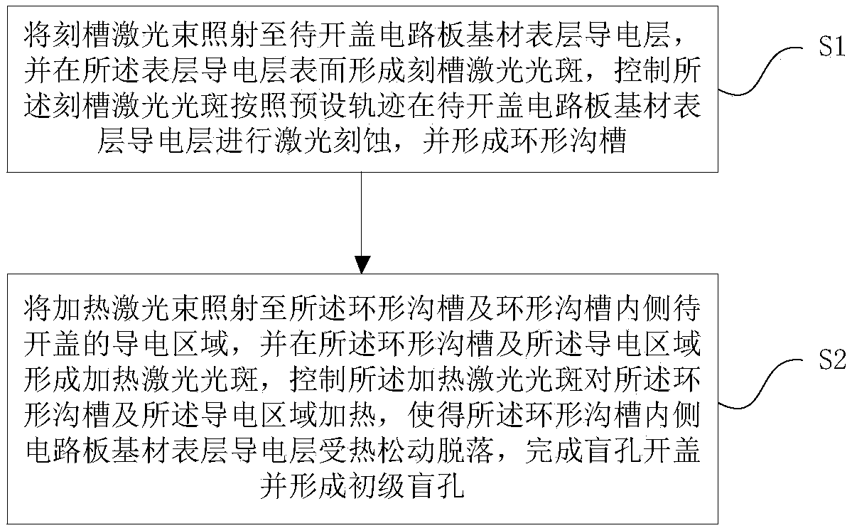
[0053] Such as figure 1 As shown, a laser blind hole uncapping method includes:

[0054] Step 1: Irradiate the groove laser beam to the surface conductive layer of the substrate of the circuit board to be opened, and form a groove laser spot on the surface of the surface conductive layer, and control the groove laser spot to follow the preset track on the cover to be opened The conductive layer on the surface of the circuit board substrate is laser etched to form an annular groove;

[0055] Step 2: irradiate the heating laser beam to the annular groove and the conductive area to be opened inside the annular groove, and form a heating laser spot on the annular groove and the conductive area, and control the heating ...


PUM

PropertyMeasurementUnit
Diameteraaaaaaaaaa

Abstract

The invention relates to a blind hole uncapping method using laser. The blind hole uncapping method comprises the steps that grooving laser beams are irradiated to a surface layer conducting layer ofa to-be-uncapped circuit board substrate, laser etching is carried out on the surface layer conducting layer of the to-be-uncapped circuit board substrate according to a preset track, and an annular groove is formed; and heating laser beams are irradiated to the annular groove and a to-be-uncapped surface layer conducting layer area on the inner side of the annular groove, heating is carried out,the surface layer conducting layer of the circuit board substrate on the inner side of the annular groove becomes loose and drops off by heating, the blind hole uncapping is finished, and a primary blind hole is formed. According to the blind hole uncapping method using the laser, the surface layer conducting layer of a circuit board is subjected to closed-loop grooving using the grooving laser beams, the annular groove is obtained, the annular groove and a conducting area in the annular groove are heated using the heating laser beams, under the action of plasma shock waves generated by actionof heating laser light spots and substance in the groove, the surface layer conducting layer of a blind hole to-be-uncapped protecting area becomes loose and drops off, the blind hole uncapping is finished, the primary blind hole is formed, and the blind hole uncapping problem is ingeniously solved.

Description

technical field [0001] The invention relates to the technical field of laser processing, in particular to a method for uncapping a laser blind hole. Background technique [0002] At present, carbon dioxide laser circuit board drilling occupies an absolute position in the field of blind hole drilling of hard boards and rigid-flex boards. Because carbon dioxide lasers do not absorb copper foil well, many of them use copper on the surface of the circuit board to open windows to expose the underlying layers. The insulating layer of the glass fiber cloth layer and the adhesive layer allows the carbon dioxide laser to directly act on the insulating layer until the lower layer is exposed to complete the blind hole drilling function. [0003] In this process, the action of removing the upper layer of copper is called blind hole uncapping. The basic requirement for blind hole uncapping is to reliably remove the surface copper skin, and it is required not to damage or evenly remove a ...

Claims


Application Information

Patent Timeline
IPC IPC(8): H05K3/00B23K26/386
CPCB23K26/386H05K3/00H05K3/0026
Inventor 张立国
Owner 武汉铱科赛科技有限公司
Why Eureka
Try Eureka