

Full-automatic induction quenching machine tool for conical face of front machine cylinder of molding machine and circuit protecting method
An induction hardening and fully automatic technology, applied in the direction of quenching devices, electrical components, electronic switches, etc., can solve the problems of large application field limitations, low equipment automation, and low production efficiency, and achieve high automation and perfect detection Control functions, fast-paced effects
- Summary
- Abstract
- Description
- Claims
- Application Information
AI Technical Summary
Problems solved by technology
Method used
Image

Examples
Embodiment 1
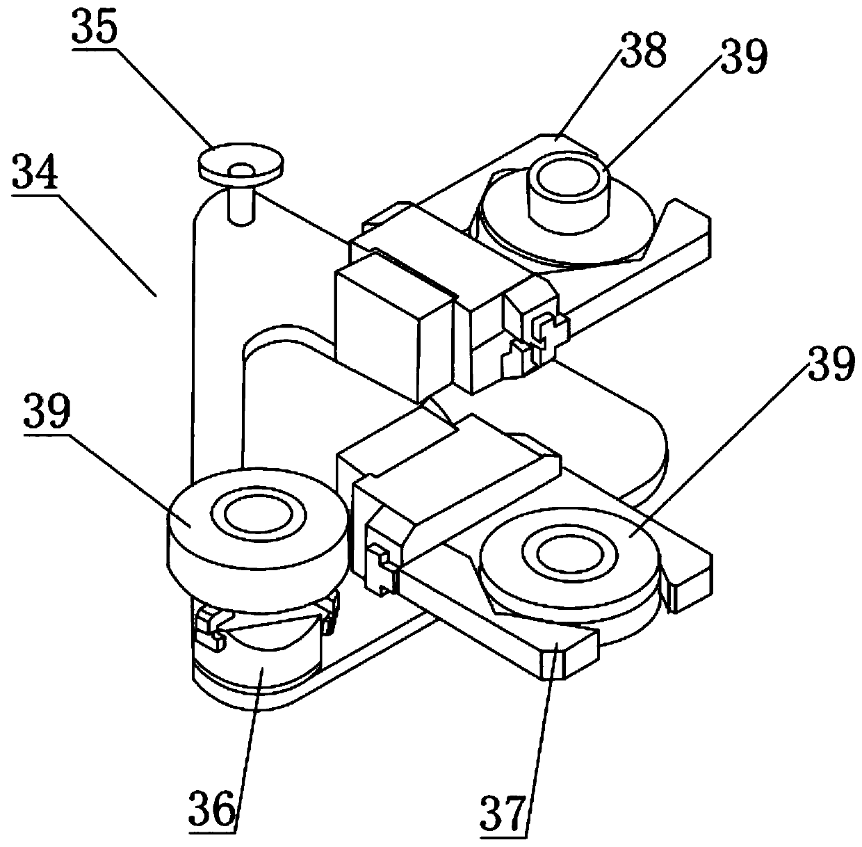
[0021] Preferred embodiment one of the present invention: the industrial automatic robot is an ABB six-axis mechanical arm robot, and the three grippers 34 installed at the end of the robot arm of the ABB six-axis robotic arm pass through the initial material gripper 36 at the same time from the special station equipment Take the front barrel of the plastic machine and place it on the pre-positioning part, then take the front barrel 39 of the plastic machine from the pre-positioning part by the pre-positioning gripper 37 and place it on the rotating drive part to rotate induction heating and rotary quenching, the quenching process After completion, the front barrel of the plastic machine is taken from the rotating drive part by the unloading gripper 38, and is transferred and placed on the vacant special-purpose station on the automatic unloading conveying roller table. The machine barrel is conveyed and dropped into the discharge box through the automatic discharge conveying r...
Embodiment 3
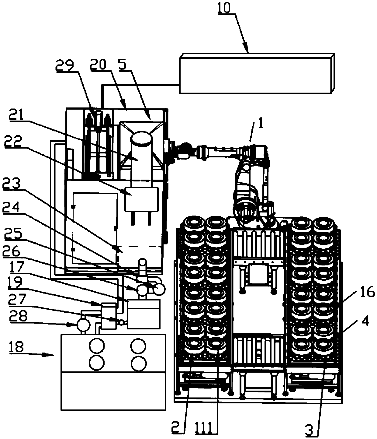
[0023] Preferred Embodiment 3 of the present invention: the quenching liquid cooling circulation system includes a liquid sump 23 for quenching liquid at the bottom of the automatic induction quenching chamber 5, and the liquid outlet pipe at the bottom of the sump 23 is formed with the surface of the metal chain rail section for absorbing induction heating The large-capacity magnetic paper bag filter 24 of the oxide skin is connected to the liquid inlet pipe, and the magnetic filter outlet pipe is connected to the liquid inlet pipe of the cartridge filter bag filter 25 for precise filtration, and the bag filter outlet pipe is It is connected with the liquid inlet pipe of the first circulating water pump 26, and the liquid outlet pipe of the first circulating water pump 26 is connected with the liquid inlet pipe of the first water storage tank. The liquid outlet pipe is communicated with the liquid inlet pipe of a plate heat exchanger 19, and the liquid outlet pipe of the plate...
Embodiment 4
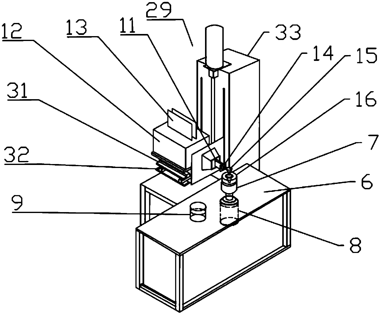
[0024] Preferred Embodiment 4 of the present invention: the three-dimensional sliding table 29 for loading the quenching transformer 12 and the compensation capacitor 13 and applied to the X, Y, and Z directions of the quenching process requirements of workpieces with different diameters includes: up and down (Z direction) The electric servo drive unit 33 in the direction, the front and rear direction (Y direction) is provided with the front and rear electric servo drive unit 32, the left and right (X direction) direction is provided with the electric servo drive unit 31, and the three-dimensional slide table 29 is used to adjust the relative distance between the inductor and the workpiece. Ensure that the integrated quick change device 15 of the sensor, water and electricity is centered and is facing the tapered surface of the front barrel 16.
[0025] Preferred Embodiment 5 of the present invention: The three-dimensional sliding table 29 with X, Y, and Z direction adjustments...
PUM
 Abstract
Description
Claims
Application Information