Gas-liquid mixing device and application thereof

A gas-liquid mixing and equipment technology, which is applied in the gas-liquid reaction process and the field of gas-liquid mixing equipment, can solve the problems of increasing the liquid mass transfer area, complex circulation process, long residence time, etc., and achieve the elimination of reaction resistance and large gas carrying capacity , Strong gas-liquid mixing ability

Active Publication Date: 2019-04-26
CHINA PETROLEUM & CHEM CORP +1
View PDF15 Cites 8 Cited by
  • Summary
  • Abstract
  • Description
  • Claims
  • Application Information

AI Technical Summary

Problems solved by technology

[0007] Aiming at the deficiencies of the prior art, the present invention provides a gas-liquid mixing device and its application, which can greatly improve the gas-liquid mixing effect, increase the dissolved and dispersed amount and the uniformity of the gas in the liquid phase, and form the "oil The "air-encapsulated" gas-liquid mixed fluid is a homogeneous phase and the state is stable, which not only can greatly increase its liquid mass transfer area, but also enable the gas-liquid reaction process to maintain a high rate continuously, solving the large number of liquid cycles in the existing technology Problems such as complex process, high material consumption and energy consumption, and long residence time

Method used


Image

  • Gas-liquid mixing device and application thereof
  • Gas-liquid mixing device and application thereof
  • Gas-liquid mixing device and application thereof

Examples


Embodiment 1

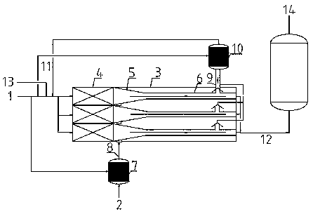
[0059] Adopt attached figure 1 According to the hydrogen dissolving equipment and the hydrogen dissolving process, the preliminary hydrogen dissolving section in the hydrogen dissolving equipment adopts a cylindrical interior filled with a rotary vane spoiler assembly, the residence time is 1.5 minutes, and the low pressure escaped hydrogen is pre-dispersed to 500 nm through the inorganic membrane tube The size of the microbubbles are mixed and dispersed with a small amount of raw material oil and then recycled. The flow rate is 0.045% of the raw material quality; the contraction angle of the accelerated hydrogen dissolving section is 15°, and the length ratio of the accelerated hydrogen dissolving section to the hydrogen releasing section is 1:5; The operating conditions for the introduction position of the hydrogen-rich liquid mixture in the accelerated hydrogen dissolution section are: the temperature is 160° C. and the pressure is 6.0 MPaG. The high-pressure hydrogen disper...

Embodiment 2

[0061] Adopt attached figure 1 In the hydrogen dissolving equipment and the hydrogen dissolving process, the preliminary hydrogen dissolving section in the hydrogen dissolving equipment adopts a static mixer structure, the model is SL-12.5 / 25-6.4-500, the residence time is 1 minute, and the low-pressure hydrogen escapes through the inorganic membrane The tube is pre-dispersed into 500nm-sized micro-bubbles and then mixed and dispersed with a small amount of raw material oil for recycling. The flow rate is 0.03% of the raw material quality; the shrinkage angle of the hydrogen dissolving section is 20°, and the length ratio of the hydrogen dissolving section to the hydrogen releasing section is accelerated It is 1:10; the operating conditions of the introduction position of the hydrogen-rich liquid mixture in the accelerated hydrogen dissolution section are: the temperature is 100°C and the pressure is 5.5 MPaG. The high-pressure hydrogen disperser uses an inorganic membrane tube...

Embodiment 3

[0063] Adopt attached figure 1 In the hydrogen dissolving equipment and the hydrogen dissolving process, the preliminary hydrogen dissolving section in the hydrogen dissolving equipment adopts a cylindrical interior filled with porous plate spoiler components, the residence time is 1.8 minutes, and the low-pressure escaping hydrogen is pre-dispersed by the inorganic membrane tube. The micro-bubbles of 1000nm size are mixed and dispersed with a small amount of raw material oil and then recycled. The flow rate is 0.015% of the raw material quality; the contraction angle of the accelerated hydrogen dissolving section is 25°, and the length ratio of the accelerated hydrogen dissolving section to the hydrogen releasing section is 1:15 ; The operating conditions for the introduction position of the hydrogen-rich liquid mixture in the accelerated hydrogen dissolution section are: the temperature is 280° C. and the pressure is 6.0 MPaG. The high-pressure hydrogen disperser uses an inor...


PUM

PropertyMeasurementUnit
angleaaaaaaaaaa

Abstract

The invention discloses a gas-liquid mixing device and application thereof. The gas-liquid mixing device comprises a gas-liquid mixing device shell, wherein a plurality of parallel gas-liquid mixing assemblies are contained in the shell; the gas-liquid mixing assemblies are of a cavity structure, and are sequentially provided with preliminary gas-liquid mixing sections, accelerating gas-liquid mixing sections and gas releasing sections in the material flow direction, and the sections communicate with one another; the accelerating gas-liquid mixing sections are of a conical contraction structure, the starting ends of the accelerating gas-liquid mixing sections are connected with high-pressure gas dispersing equipment, gas phase outlets for releasing escaped gas are formed in the middle rearpart of the gas releasing sections, liquid phase outlets are formed in the tail ends of the gas releasing sections. The 'oil-covering-gas type' gas-liquid mixed fluid formed by the gas-liquid mixingdevice is homogeneous and stable, the liquid mass transfer area can be greatly increased, the gas-liquid reaction process can be enabled to continuously maintain a higher rate, and the problems of large amount of liquid circulation, high material consumption and energy consumption, long residence time and the like existing in the prior art are solved.

Description

Technical field [0001] The invention belongs to the field of gas-liquid mass transfer reactions, in particular to a new type of gas-liquid mixing equipment and its application method, which can be widely used in gas-liquid reactions in the fields of petroleum, chemical industry, light industry, medicine, environmental protection, etc. process. Background technique [0002] In the fields of petroleum, chemical industry, light industry, medicine, environmental protection, etc., many fixed-bed gas-liquid-solid three-phase reaction processes are involved. The solid is the catalyst, and the gas-liquid two-phase is passed in the form of trickle. The catalyst bed is therefore also called a trickle bed reactor. [0003] In a trickle bed reactor, the gas needs to be transferred from the gas phase to the liquid phase, and then co-adsorbed on the surface of the catalyst to react under the action of the active center of the catalyst. In general, in order to strengthen the mass transfer of th...

Claims


Application Information

Patent Timeline
Patent Type & Authority Applications(China)
IPC IPC(8): B01F3/04B01F13/10
CPCB01F23/2131B01F23/213B01F23/21322B01F33/85
Inventor 杨秀娜金平王昊辰阮宗琳齐慧敏
Owner CHINA PETROLEUM & CHEM CORP
Why Eureka
Try Eureka