A kind of solvent displacement condensation tower and the method for producing anhydrous formaldehyde

A solvent and condensation technology, applied in the field of solvent displacement condensation tower and production of anhydrous formaldehyde, can solve the problem of low yield of formaldehyde in one pass, achieve the effect of increasing yield of formaldehyde in one pass, improving unit utilization rate, and simple structure

Active Publication Date: 2021-08-27
潍坊惠丰化工有限公司 +1
View PDF11 Cites 0 Cited by
  • Summary
  • Abstract
  • Description
  • Claims
  • Application Information

AI Technical Summary

Problems solved by technology

U.S. patents US2848500 and US6414196 propose a method for producing high-purity formaldehyde gas, using various alcohols as solvents to prepare formaldehyde solvent condensate and using an evaporator for pyrolysis to obtain high-purity formaldehyde gas, but the condensation is performed in a batch stirred tank The yield of one-way formaldehyde is not high when performing distillation and dehydration after condensation, and there are still about 4% formaldehyde remaining in the solvent during pyrolysis

Method used


Image

  • A kind of solvent displacement condensation tower and the method for producing anhydrous formaldehyde
  • A kind of solvent displacement condensation tower and the method for producing anhydrous formaldehyde
  • A kind of solvent displacement condensation tower and the method for producing anhydrous formaldehyde

Examples


Embodiment 1

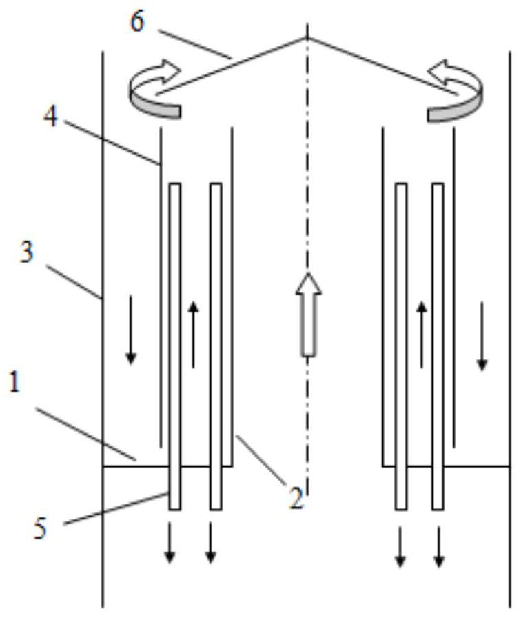
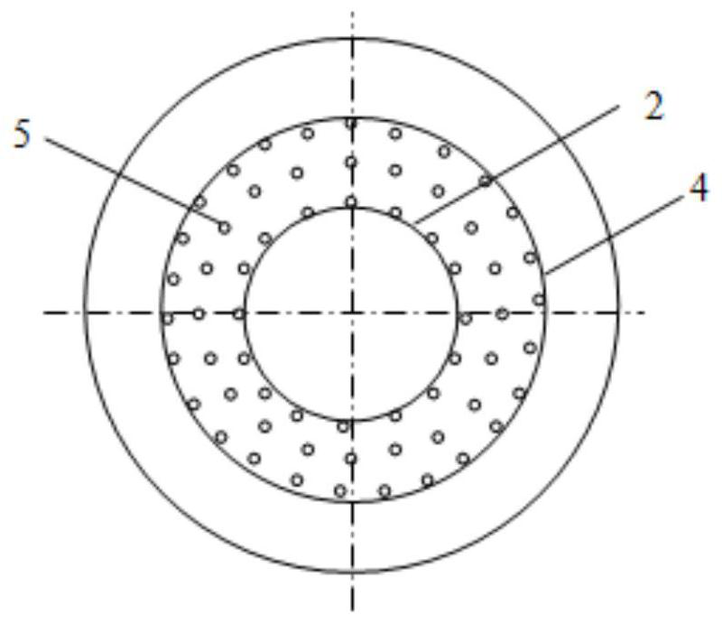
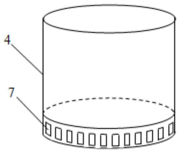
[0052] as attached figure 1 , 2 , As shown in 3, a ring-shaped diversion distribution groove is set in a rectification tower with an inner diameter of φ200mm. The specific dimensions are: the outer diameter of the annular plate 1 is φ200mm, the inner diameter is φ60mm, the diameter of the circular baffle 4 is φ140mm; the height of the circular air riser 2 and the circular baffle 4 is 240mm, and the inner diameter of the downcomer 5 is 4mm , close to the outer side of the circular riser 2 and the inner side of the circular baffle 4, a total of 18 pieces are arranged in two circles, and the height of the downcomer 5 is 180mm; the openings 7 at the bottom of the circular baffle 4 are circular holes at intervals. 8mm, a total of 20, the hole spacing is 22mm.

[0053] During installation, assemble the annular diversion distribution groove of the above structure and CY700 corrugated wire mesh packing into a tower section with flange connections at both ends. The height of the corr...

Embodiment 2

[0055] as attached figure 1 , 2 As shown in , 3, another annular diversion distribution groove is set in a rectification tower with an inner diameter of φ200mm. The specific dimensions are: the outer diameter of the annular plate 1 is φ200mm, the inner diameter is φ60mm, the diameter of the circular baffle 4 is φ140mm; the height of the circular air riser 2 and the circular baffle 4 is 500mm, and the inner diameter of the downcomer 5 is 4mm , close to the outer side of the circular riser 2 and the inner side of the circular baffle 4, a total of 18 pieces are arranged in two circles, and the height of the downcomer 5 is 440mm; 8mm, a total of 20, the hole spacing is 22mm.

[0056] During installation, assemble the annular diversion distribution groove of the above structure and CY700 corrugated wire mesh packing into a tower section with flange connections at both ends. The height of the corrugated wire mesh packing in the tower section is 1.4m.

Embodiment 3

[0058] Place one section of the tower section assembled in Example 1 on the upper end, place two identical sections of the tower section assembled in Example 2 in the middle and the lower end, and rely on flange connection to form a main tower section of a solvent displacement condensation tower, equipped with a top condenser 14. Phase separation tank 15 and tower bottom reboiler 19. The condenser 14 has a heat transfer area of ​​4 m 2 and is cooled with circulating water; the reboiler 19 has a heat transfer area of ​​5 m 2 and is heated with heat transfer oil; the volume of the phase separation tank 15 is 75 L.

[0059] Attached Figure 4 Experiments are carried out on the process of the above-mentioned technology, operated under normal pressure, the concentration of formaldehyde solution is 48.5%, the flow rate is 20kg / h, the feed temperature is 80°C, and the feed position is the top of the second tower section; the solvent is benzyl alcohol, and the flow rate is 48kg / h , t...


PUM

PropertyMeasurementUnit
boiling pointaaaaaaaaaa
heightaaaaaaaaaa

Abstract

The invention discloses a solvent displacement condensation tower and a method for producing anhydrous formaldehyde, and mainly relates to the technical field of organic synthesis. The solvent displacement condensation tower is composed of several annular diversion distribution grooves and packing sections alternately, and the annular diversion distribution groove includes outer Tank, inner tank and central riser and downcomer arranged in the inner tank. When in use, the external feed and the liquid flowing down from the top of the tower first flow down the outer tank, pass through the opening at the bottom of the baffle into the inner tank and then flow upward, and finally flow from the multiple downcomers in the inner tank to the ring guide. The packing surface below the flow distribution groove performs mass exchange with the gas phase. After the liquid flows through the packing section, it enters the outer tank of the next-level annular diversion tank, and then flows through the inner tank and downcomer in turn to enter the next packing section until it reaches the bottom of the tower. The gas rises along the packing gap in the tower and enters the gas riser of the annular diversion distribution groove, bypasses the umbrella-shaped baffle and enters the upper packing layer, and then gradually flows out from the top of the tower.

Description

technical field [0001] The invention mainly relates to the technical field of organic synthesis, in particular to a solvent replacement condensation tower and a method for producing anhydrous formaldehyde. Background technique [0002] Formaldehyde is used as a basic chemical raw material in a wide range of applications, but the use of formaldehyde is generally carried out under the condition of being dissolved in water. In the field of synthesis of some pharmaceutical intermediates or fine chemicals, the reaction often requires an anhydrous environment. At this time, most of them use paraformaldehyde pyrolysis to obtain formaldehyde raw materials. Paraformaldehyde forms a chain structure, and the capping groups at both ends are hydroxyl and hydrogen. After pyrolysis to form monomer formaldehyde, the capping groups naturally form water molecules. Therefore, the water content of paraformaldehyde pyrolysis often still reaches 2~ About 4%, still produces not small influence to...

Claims


Application Information

Patent Timeline
Patent Type & Authority Patents(China)
IPC IPC(8): B01D3/00B01D3/14B01J19/00C07C45/82C07C47/04
Inventor 付冠卿王成习孙玉石
Owner 潍坊惠丰化工有限公司
Why Eureka
Try Eureka