Control system and method based on two-stage bidirectional converter

A bidirectional converter, control system technology, applied in control/regulation systems, DC power input conversion to DC power output, instruments, etc., can solve problems such as system flexibility and poor configuration, improve power quality, extend Effective working hours and the effect of improving economic efficiency

Inactive Publication Date: 2019-05-03
SHAANXI UNIV OF SCI & TECH
View PDF5 Cites 6 Cited by
  • Summary
  • Abstract
  • Description
  • Claims
  • Application Information

AI Technical Summary

Problems solved by technology

[0004] However, the above-mentioned disadvantages are the disadvantages of poor flexibility and configuration of the system.

Method used


Image

  • Control system and method based on two-stage bidirectional converter
  • Control system and method based on two-stage bidirectional converter
  • Control system and method based on two-stage bidirectional converter

Examples


Embodiment 1

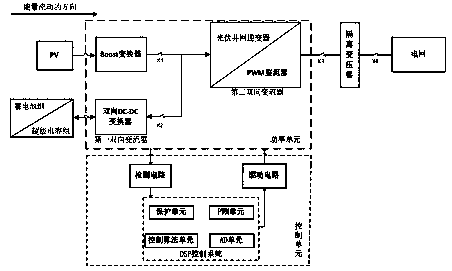
[0028] The embodiment of the first aspect of the present invention provides a control system used in the technical field of energy storage and energy exchange, specifically a control system based on a two-stage bidirectional converter. attached figure 1 A structural block diagram of a two-stage bidirectional converter provided by the present invention.

[0029] The system consists of photovoltaic modules, Boost converter, DC circuit breakers K1 and K2, second bidirectional converter (DC / AC converter and AC / DC converter), AC contactor K3, isolation transformer (220V / 380V), It is composed of AC circuit breaker K4, the first bidirectional converter (bidirectional DC / DC converter), battery and supercapacitor module, and control unit.

[0030] figure 1 In China, photovoltaic grid-connected inverters belong to DC / AC converters, and PWM rectifiers belong to AC / AC converters. This patent is unified into photovoltaic grid-connected inverters and PWM rectifiers.

[0031] The power un...

Embodiment 2

[0040] The embodiment of the second aspect of the patent of the present invention also provides a control method for a two-stage bidirectional converter. as attached figure 2 Shown is a control mode selection diagram of a two-stage bidirectional converter. Firstly, it detects the light intensity and receives the power grid scheduling command, and selects the appropriate working mode according to the range of the light intensity and the power grid scheduling situation.

[0041] Set the threshold H and L of illuminance, and select the working state according to the illuminance parameters measured in real time. The peak of power consumption or the low valley of power consumption is judged by the power grid according to the weight of the load. When the power demanded by the power load is much greater than the power generated, it is at the peak of power consumption, and a large amount of electric energy needs to be generated to meet the load demand. The light intensity parameter...


PUM


Abstract

The invention provides a control system and method based on a two-stage bidirectional converter. The system is composed of a power unit and a control unit. The power unit comprises a Boost converter and two bidirectional converters, wherein the input end of the Boost converter is connected with the output end of a photovoltaic module, and the output end of the Boost converter is connected to a DCbus. A storage battery and a super-capacitor module are used as the input end of the first bidirectional converter, and the output end of the first bidirectional converter is connected to the DC bus.The input end of the second bidirectional converter is connected with the DC bus, the output end of the second bidirectional converter is connected with the low-voltage end of an isolation voltage device, wherein the high-voltage end of the isolation voltage device is connected with a power grid through an AC bus. The control unit collects a signal fed back by the power unit and transmits a control instruction to the power unit. According to the invention, the peak clipping and valley filling are carried out on the power grid system according to the illumination intensity and the power grid dispatching instruction.

Description

technical field [0001] The invention relates to the technical field of energy storage and energy exchange, in particular to an energy storage two-stage bidirectional converter and a control method thereof, which are applied to microgrids. Background technique [0002] As energy security and environmental issues become increasingly serious, the development of new energy power generation and micro-grid technology has become an international trend. Battery energy storage systems can be used as a medium for flexible transmission of electric energy such as new energy power generation and micro-grid technology, making new energy power generation and micro-grid technology The power transmission of technology is more stable and flexible, making the original almost completely "rigid" system "flexible", so it has received widespread attention from all over the world in recent years. [0003] The battery energy storage system mainly uses a two-stage bidirectional converter. Its main fu...

Claims


Application Information

Patent Timeline
Patent Type & Authority Applications(China)
IPC IPC(8): H02J3/32H02J3/38H02J7/35H02M3/335
CPCY02E70/30Y02E10/56
Inventor 王素娥吴永斌郝鹏飞
Owner SHAANXI UNIV OF SCI & TECH
Why Eureka
Try Eureka