Pressurized vacuum flexible tubular well dewatering and drainage system and construction method thereof

A vacuum flexible drainage system technology, which is applied in infrastructure engineering, soil protection, construction, etc., can solve the problems of drainage failure, long drainage path, and easy silting of the filter layer, so as to reduce the radius of precipitation and reduce the project cost. The effect of reducing the cost and shortening the precipitation time

Inactive Publication Date: 2019-05-17
王琪
View PDF0 Cites 5 Cited by
  • Summary
  • Abstract
  • Description
  • Claims
  • Application Information

AI Technical Summary

Problems solved by technology

Improving the strength of the soil in the passive area of ​​the foundation pit through precipitation will save a lot of engineering costs, because the reinforcement measures for soft soil inside the foundation pit to improve the resistance of the passive area of ​​the foundation pit, such as mixing pile reinforcement or high-pressure rotary grouting pile and injection The cost of slurry reinforcement is high and the time is long
[0004] Excavating and transporting the soft soil with high water content in the foundation pit not only requires high excavation costs, but also increases the difficulty of excavation and transportation of the excavator. It is necessary to lay special roads to realize the excavation and transportation of this type of soil.
In addition, during the transportation of the soil, there will be problems of mud and water spilling, causing environmental pollution, and at the same time, it will also bring difficulties in stacking the spoil field
[0005] At present, it is a big problem to drain the water in the silt and muddy clay, because the permeability of this kind of soft clay is very poor, and the water in it is difficult to drain in a short time
At present, the vacuum tube well method is used for dewatering and drainage, and each tube well needs to achieve dewatering and drainage in silt soil with an area of ​​more than 100 square meters, which is difficult to meet the requirements of the project
The filter tube used in the current vacuum tube well is made of steel pipe or plastic tube after manual drilling, and the outer side is wrapped with gauze. The aperture is relatively large, and clay particles can easily enter the filter tube through these holes.
Smaller filter holes are often occupied by small clay particles, which block the filter pipe and filter screen, and the drainage is completely ineffective.
In addition, the sand filter layer outside the filter pipe is made by sand blasting during well drilling, and its quality cannot be controlled; the sealing layer made of clay particles is even more difficult to achieve a good plugging effect, and cannot form a high of vacuum
[0006] Due to the use of vacuum tube wells for drainage in silt and muddy soil, the cost of materials and construction is relatively high. When the spacing is large, the drainage path is long; the filter layer is easy to be silted, and the drainage effect achieved is very poor.

Method used


Image

  • Pressurized vacuum flexible tubular well dewatering and drainage system and construction method thereof
  • Pressurized vacuum flexible tubular well dewatering and drainage system and construction method thereof
  • Pressurized vacuum flexible tubular well dewatering and drainage system and construction method thereof

Examples


Embodiment Construction

[0039] In order to make the technical means, creative features, goals and effects achieved by the present invention easy to understand, the present invention will be further described below in conjunction with specific illustrations.

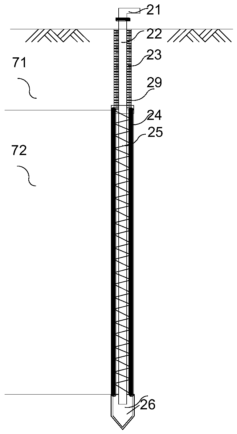
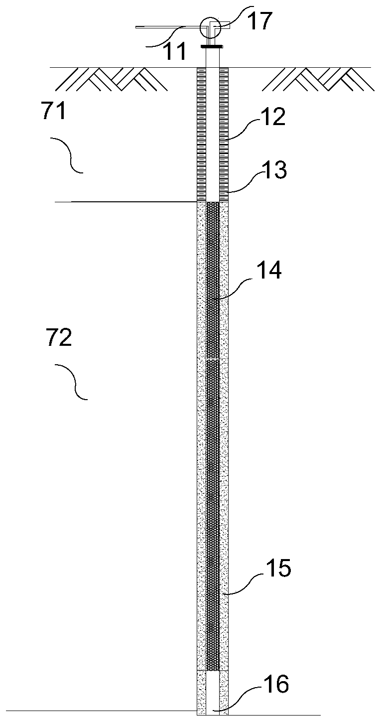
[0040] In order to fully illustrate the working principle of this new type of pressurized drainage system, we will make a structural section of a pressurized vacuum flexible tube well as shown in figure 1 Compared with the traditional vacuum tube well profile such as figure 2 List them together. from figure 2 It can be seen that the traditional vacuum tube well is composed of a steel pipe 12, a porous steel pipe wrapped around a filter pipe 14, a granular filter material 15 and a sealing clay sphere 13 at the drainage part, and a vacuum tube 11 and a drain pipe 17 are arranged in the well pipe. When it is a tube well with a larger diameter, a submersible pump is directly provided inside for drainage. The bottom of the tube well is provided ...


PUM


Abstract

The invention discloses a pressurized vacuum flexible tubular well dewatering and drainage system and a construction method thereof. The vacuum flexible tubular well comprises a tube shoe, a filteringtype flexible tube, a sealing tube, an air pumping and water draining tube and a connecting joint, wherein the tube shoe is positioned at the lower part of the vacuum flexible tubular well; the upperpart of the tube shoe is in shape of a hollow tube, and the lower part of the tube shoe is in shape of a tube cone; and the bottom part of the tube shoe is sealed; the filtering type flexible tube isa hollow circular tube; a tube body is prepared by coiling an elastic framework with porous filtering cloth; the sealing tube is a hollow hard tube and is positioned at the upper part of the filtering type flexible tube; and the air pumping and water draining tube is a hollow hard tube and is positioned in the filtering type flexible tube. The dewatering and drainage system comprises a pluralityof pressurized vacuum tubes, a tubular well connecting tube, an air and liquid separating tank, a one-way overflowing valve, a main water draining tube, a vacuum pump and an air compressor. The systemachieves the purpose of quickly dewatering and draining water.

Description

technical field [0001] The invention relates to the fields of foundation reinforcement, deep foundation pit reinforcement and soft soil excavation, in particular to a method for rapid drainage and consolidation from silt soft soil. Background technique [0002] When constructing roads and buildings in soft soil areas, it is necessary to strengthen the silt soft soil. The most common method is to quickly increase the strength or bearing capacity of the silt soft soil through drainage and consolidation. However, the current Both the sand well treatment method and the vacuum drainage method have problems such as long drainage time, difficult drainage and silting of the drainage plate, which are difficult to meet the engineering needs. [0003] During the development of underground space, a large number of deep foundation pits appear continuously. Due to the existence of groundwater, the construction of foundation pit engineering often faces the problem of dewatering and draina...

Claims


Application Information

Patent Timeline
IPC IPC(8): E02D3/10
Inventor 刘斐然张越
Owner 王琪
Why Eureka
Try Eureka