Embedded mechanical hydraulic transmission power generation control system and method

A mechanical-hydraulic transmission and power generation control technology, which is applied in fluid pressure actuation system testing, fluid pressure actuation system components, mechanical equipment, etc., can solve the problem of inability to realize nonlinear correction of sensor output characteristics and inability to effectively reduce sensor dynamic measurement Errors, the adjustment of non-power generation strength, etc., to achieve clear design ideas, save manpower, and save time

Active Publication Date: 2019-05-21
XIJING UNIV
View PDF3 Cites 0 Cited by
  • Summary
  • Abstract
  • Description
  • Claims
  • Application Information

AI Technical Summary

Problems solved by technology

[0004] (1) The existing technology needs to be further improved in terms of hydraulic transmission power generation, and cannot be intelligently controlled or adjusted for power generation. The function is single and inconvenient to use
[0005] (2) The current sensor in the prior art detects the magnitude of the current generated by the generator, which is easily affected by temperature and cannot realize the nonlinear correction of the output characteristics of the sensor
[0006] (3) In the process of the pressure sensor detecting the hydraulic oil pressure in the hydraulic system in the prior art, the pressure sensor adopts the traditional algorithm, which cannot effectively reduce the dynamic measurement error of the sensor, and improve the high degree of parallelism, stability and global search ability
[0007] (3) In the process of the pressure sensor detecting the hydraulic oil pressure in the hydraulic system in the prior art, the pressure sensor adopts the traditional algorithm, which cannot effectively reduce the dynamic measurement error of the sensor and improve the global search ability

Method used


Image

  • Embedded mechanical hydraulic transmission power generation control system and method
  • Embedded mechanical hydraulic transmission power generation control system and method
  • Embedded mechanical hydraulic transmission power generation control system and method

Examples


Embodiment Construction

[0041] The technical solutions of the present invention will be clearly and completely described below in conjunction with specific embodiments of the present invention. Apparently, the described embodiments are only some of the embodiments of the present invention, not all of them. Based on the embodiments of the present invention, all other embodiments obtained by persons of ordinary skill in the art without making creative efforts belong to the protection scope of the present invention.

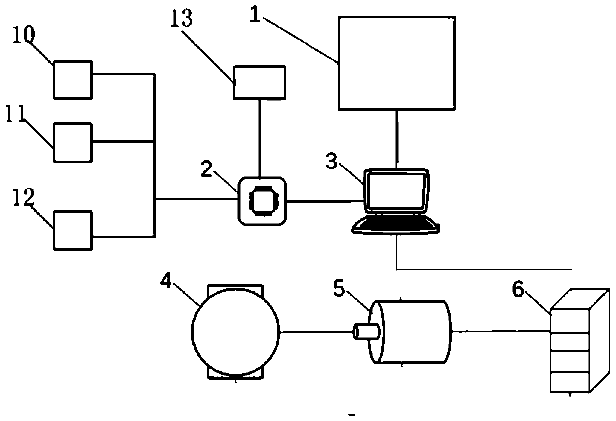
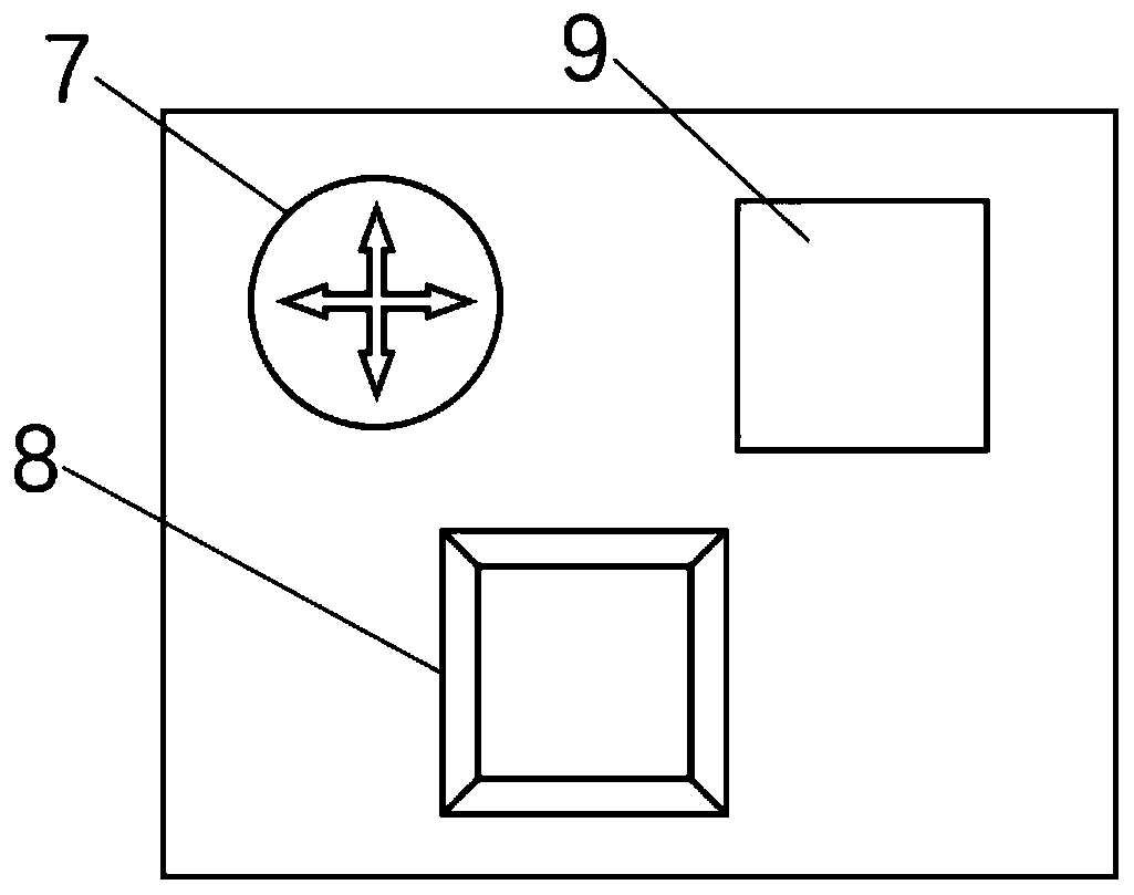
[0042] Such as Figure 1 to Figure 2 As shown, the embedded mechanical-hydraulic transmission power generation control system provided by the embodiment of the present invention includes: control element 1, single-chip microcomputer 2, main control machine 3, generator 4, hydraulic oil pump 5, gearbox 6, directional control valve 7, Flow control valve 8, pressure control valve 9, pressure sensor 10, flow rate sensor 11, current sensor 12, wireless signal transmitter 13.

[0043] The contr...


PUM


Abstract

The invention belongs to the technical field of hydraulic transmission power generation and discloses an embedded mechanical hydraulic transmission power generation control system and method. The method comprises the steps that a power supply is powered on to start a hydraulic oil pump to provide hydraulic energy for a power generator, the power generator converts hydraulic energy into electric energy to supply power to an external device; the pressure of hydraulic oil in a hydraulic system is detected through a pressure sensor, the flow velocity of output hydraulic oil of the hydraulic oil pump is detected through a flow velocity sensor, and the magnitude of current generated by the power generator is detected through a current sensor; the above detected data are transmitted to a single-chip microcomputer, and the single-chip microcomputer conducts data processing on the data; and a main controller controls relevant control valves and generate different magnitudes of current to adaptto different power demands. The embedded mechanical hydraulic transmission power generation control system and method provided by the invention have the advantages that the design thinking is clear; the functions are diversified; intelligent control can be implemented; remote control is realized; and different velocities can be adjusted.

Description

technical field [0001] The invention belongs to the technical field of hydraulic transmission power generation, and in particular relates to an embedded mechanical hydraulic transmission power generation control system and method. Background technique [0002] At present, as a widely used technology, hydraulic pressure has broad prospects in the future. With the in-depth development of computers, the hydraulic control system can be combined with intelligent control technology, computer control technology and other technologies, so that it can play a role in more occasions, and can also complete the expected more delicately and flexibly. control tasks. However, the existing technology still needs to be further improved in terms of hydraulic transmission power generation, and cannot be intelligently controlled, and cannot be adjusted for power generation, and has a single function and is inconvenient to use. [0003] In summary, the problems in the prior art are: [0004] (...

Claims


Application Information

Patent Timeline
IPC IPC(8): F15B21/08F15B19/00F16H47/00G06N3/08G06N3/12G06N10/00
Inventor 赵金国
Owner XIJING UNIV
Why Eureka
Try Eureka