
Synchronous motor parameter test and measurement method

A technology of synchronous motors and measurement methods, which is applied in the field of motor testing, can solve problems such as the inability to measure synchronous motor parameters at the same time, and achieve the effect of reducing equipment requirements

Active Publication Date: 2019-05-21
HUAZHONG UNIV OF SCI & TECH
View PDF5 Cites 0 Cited by
  • Summary
  • Abstract
  • Description
  • Claims
  • Application Information

AI Technical Summary

Problems solved by technology

[0003] Aiming at the defects of the prior art, the purpose of the present invention is to provide a method for testing and measuring the parameters of synchronous motors, aiming to solve the problem that the existing method for testing and measuring the parameters of synchronous motors cannot measure synchronous motors at the same time in the case of non-rotor positioning in the static state of the motor. d. Problems with all parameters in the q-axis equivalent circuit

Method used


Image

  • Synchronous motor parameter test and measurement method
  • Synchronous motor parameter test and measurement method
  • Synchronous motor parameter test and measurement method

Examples


Embodiment Construction

[0053] In order to make the object, technical solution and advantages of the present invention clearer, the present invention will be further described in detail below in conjunction with the accompanying drawings and embodiments. It should be understood that the specific embodiments described here are only used to explain the present invention, not to limit the present invention.

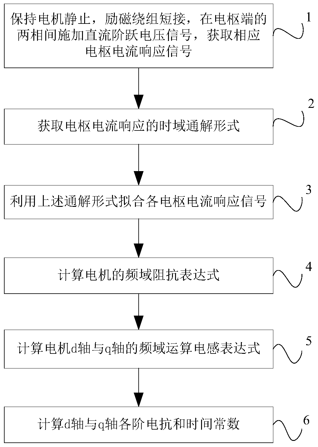
[0054] Such as figure 1 As shown, the present invention provides a method for testing and measuring synchronous motor parameters, including:

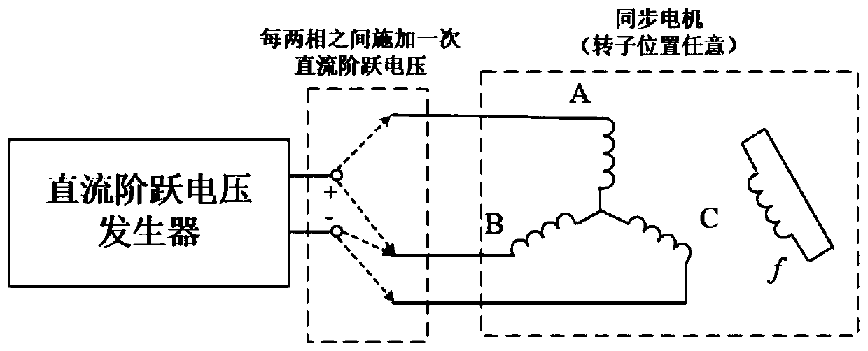
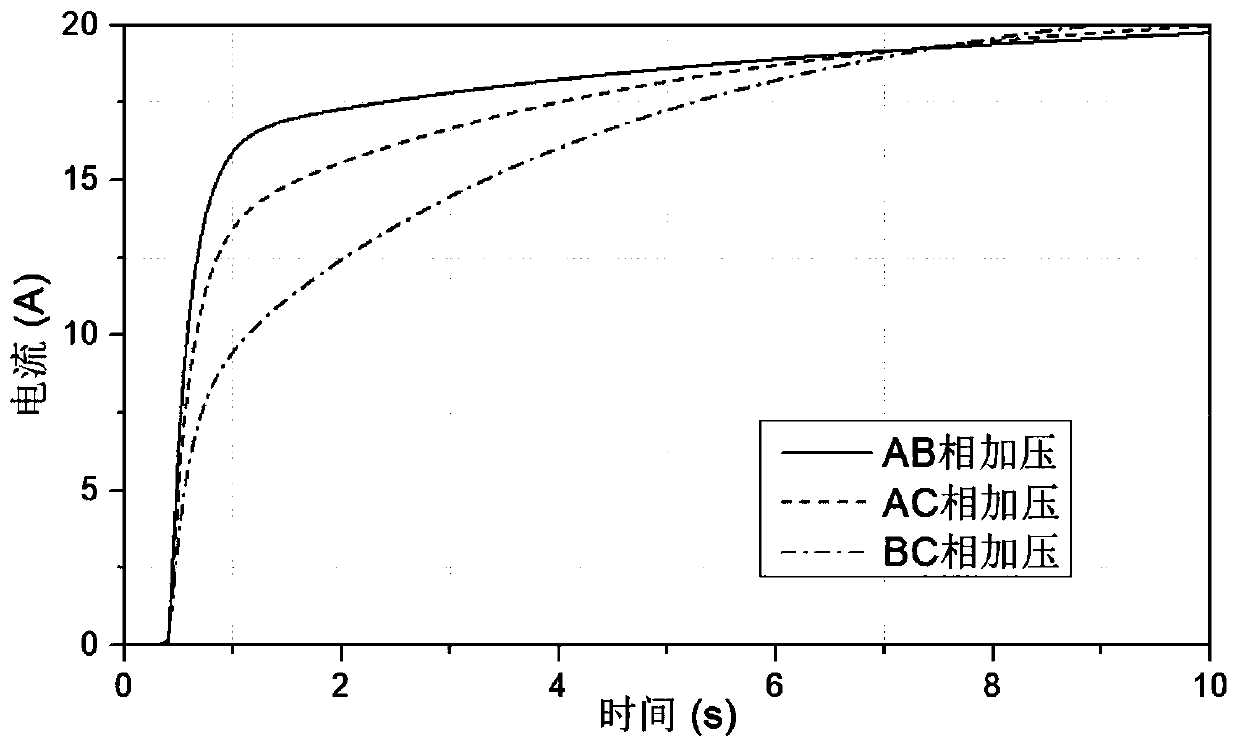
[0055] (1) When the motor is stationary and the field winding is short-circuited, such as figure 2 As shown in the wiring diagram, the same DC step voltage signal is applied between phases A, B, B, C and phases A, C of the armature in turn, and the armature current of the motor in the transient process is recorded to obtain the corresponding The armature current responds to signals such as image 3 shown;

[0056] It needs to be specially pointed out th...


PUM


Abstract

The invention discloses a synchronous motor parameter test and measurement method. The method comprises steps: when the motor is stationary and an excitation winding is short-circuited, the same DC step voltage signals are applied between different two phases of an armature end in turn, the armature current of the motor during a transient process is recorded, and corresponding armature current response signals are acquired; motor d-axis and q-axis DC step voltage signals are used to obtain the time domain general solution form of the armature current response of a rotor at any position; the time domain general solution form of the armature current response is used to fit the acquired armature current response signals, and the fit armature current response signals are converted to a frequency domain expression; and according to the frequency domain expression of each armature current response signal and the DC step voltage signal, the impedance expression of each frequency domain of themotor, motor d-axis and q-axis frequency domain operation inductance and each-step inductance and time constant are calculated. All parameters in the d and q-axis equivalent circuit of the synchronous motor can be measured simultaneously under the operation without rotor positioning.

Description

technical field [0001] The invention belongs to the technical field of motor testing, and more specifically relates to a parameter test and measurement method of a synchronous motor. Background technique [0002] Accurate measurement of synchronous motor parameters is of great significance for motor protection setting and performance evaluation. Usually, performance parameters are defined according to the d and q axes of synchronous motors, specifically including the inductance and time constant of each order of d and q axes. At present, the main test methods for extracting the equivalent model parameters of d and q axes of synchronous motors include three-phase sudden short circuit test, voltage recovery test and static frequency response test. Among them, the most widely used is the three-phase sudden short-circuit test, that is, the motor is subjected to a three-phase sudden short-circuit at the motor end under the rated speed and specific no-load voltage, and the relevan...

Claims


Application Information

Patent Timeline
IPC IPC(8): G01R31/34
Inventor 周理兵马一鸣王晋肖洋
Owner HUAZHONG UNIV OF SCI & TECH
Learn More