Plant fiber shearing device, shearing method and shearing device manufacturing method

A shearing device and plant fiber technology, which is applied in the field of plant fiber shearing devices, can solve problems such as easy blockage of screen gaps, low processing efficiency, and limited feed particle size, and achieve orderly advancement and regular shearing, avoiding The effect of shearing powder and coarse fibers, reducing resistance and limiting damage

Active Publication Date: 2019-06-07
CHANGAN UNIV +3
View PDF13 Cites 2 Cited by
  • Summary
  • Abstract
  • Description
  • Claims
  • Application Information

AI Technical Summary

Problems solved by technology

The vertical jaw crusher changes the grinding action into rubbing action, but the feeding port is very small, and the raw material needs to be crushed or cut short before feeding, and it is difficult to process rough and hard raw materials, and the processing efficiency is not high
The quality of the fiber prepared by the blade breaker is good, but the input particle size is also limited, and the equipment is intermittently processed, so the preparation efficiency is low, so it can only be used as a laboratory fiber processing equipment
The hammer mill has no requirements on the feed particle size, but when crushing sticky and wet materials, it is easy to block the sieve gap, so it is easy to cause downtime and affect production efficiency
[0005] When the above fiber processing equipment cuts plant fibers, the principle is to achieve random and irregular crushing and cutting of fibers through high-speed rotating cutting parts. The principle is similar to stirring and mixing, which will lead to repeated repetition of some fibers. The first cutting becomes powder, while some fibers are not cut and become coarse fibers, the fiber fineness and length are uneven, the cutting effect is uneven, and the quality of the final product cannot be guaranteed; and in this irregular movement process, the plant The violent collision and rubbing between the fiber and the cutting parts and between the plant fibers will cause the structural damage of the fiber itself, which will affect the mechanical properties of the fiber
In addition, the existing plant fiber shearing equipment still has problems such as easy passivation of the tool, poor corrosion resistance, and serious tool wear.

Method used


Image

  • Plant fiber shearing device, shearing method and shearing device manufacturing method
  • Plant fiber shearing device, shearing method and shearing device manufacturing method
  • Plant fiber shearing device, shearing method and shearing device manufacturing method

Examples


Embodiment 1

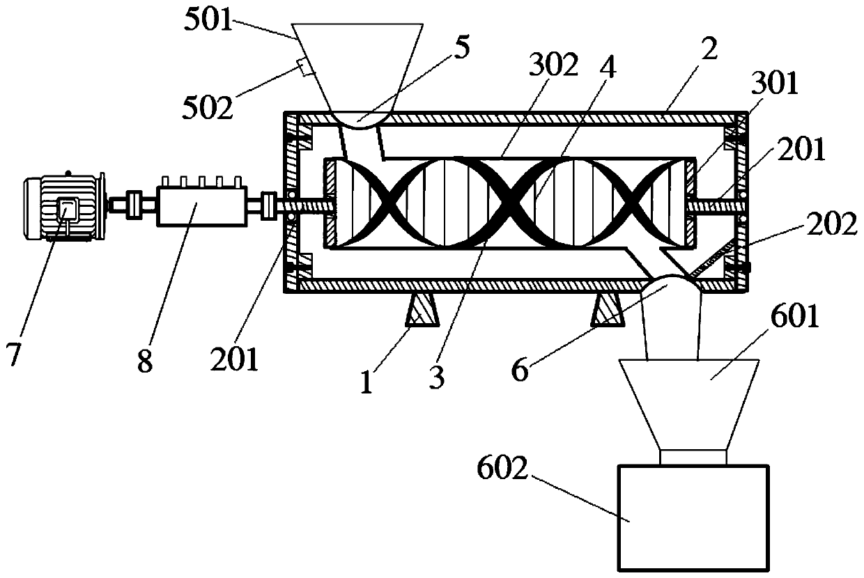
[0050] refer to figure 1 , a plant fiber shearing device of the present invention, comprising a support 1, a shear box 2 is installed on the support 1, and a double-helix shearing mechanism is arranged in the shear box 2; The left end of the top side plate is provided with a feed port 5, and the right end of the bottom side plate of the shear box 2 is provided with a discharge port 6; the left side plate of the shear box 2 is provided with a shaft hole, and the double The spiral shearing mechanism is connected with a power mechanism through a rotating shaft 201 , and the rotating shaft 201 passes through the shaft hole and extends out of the shearing box 2 .

[0051] In the above embodiments, the bracket 1 is used to support and fix the shearing box 2, and the power mechanism is used to provide power for the rotation of the double helix shearing mechanism. The power mechanism outside the shearing box 2 passes through the shaft hole and shears the One end of the double-helix s...

Embodiment 2

[0081] Below in conjunction with specific embodiment, the present invention will be further described:

[0082] A method for manufacturing a plant fiber shearing device, comprising the following steps:

[0083] Step 1, using resin to prepare a shear box;

[0084] Step 2, use 4Cr13 stainless steel to obtain castings by casting, and perform stress relief annealing on the castings. The process of stress relief annealing is: heating to 500°C at a heating rate of 100°C / h, holding for 4h, and then heating at 20°C / h~50°C / h Cool at a rate of h to 300°C, and then take out the casting for air cooling to obtain the primary product of the double-screw conveying rod; correspondingly set threaded holes on the two screw rods of the primary product of the double-screw conveying rod to obtain the double-screw conveying rod.

[0085] 4Cr13 stainless steel material and forging process are used to prepare the knife blank. The knife blank is kept at 1070°C for 2h, quenched in an oil bath, then ta...

Embodiment 3

[0089] A plant fiber shearing method, comprising the following steps:

[0090] Step 1, wash the bagasse with a length of 3-5cm, remove surface impurities, and then soak in water for 2 days to obtain the material to be sheared;

[0091] Step 2, adding the material to be sheared into the plant fiber shearing device manufactured in Example 2 for shearing, the speed of the double-screw conveying rod is set to 1500r / min, and after the shearing is completed, it is dried at 105°C to a constant weight. Obtain bagasse products.


PUM


Abstract

The invention discloses a plant fiber shearing device, a shearing method and a shearing device manufacturing method. The plant fiber shearing device comprises a bracket. A shearing box is arranged onthe bracket. A twin-screw shearing mechanism is arranged in the shearing box. A feeding opening is formed in the left end of a top side plate of the shearing box, a discharging opening is formed in the right end of a bottom side plate of the shearing box, and a shaft hole is formed in a left side plate of the shearing box. A power mechanism is connected to the twin-screw shearing mechanism througha rotating shaft. The rotating shaft penetrates through the shaft hole and extends out of the shearing box. By means of the plant fiber shearing device, the shearing method and the shearing device manufacturing method, ordered and regular cutting of plant fibers can be realized, so that the cutting fineness and lengths of the plant fibers can be controllable, and the cutting quality and production efficiency of the plant fibers are guaranteed; and meanwhile, severe collision between the plant fibers and a cutting part and severe collision between the plant fibers in the cutting process are greatly relieved, the structures of the plant fibers are prevented from being damaged, and the mechanical property of the plant fibers is ensured. The shearing method is simple, and the device manufacturing method ensures the stability of the structure.

Description

technical field [0001] The invention relates to the technical field of plant fiber processing, in particular to a plant fiber shearing device, a shearing method and a manufacturing method of the shearing device. Background technique [0002] my country's plant fibers are widely distributed and have promising application prospects, but the per capita forest resources are seriously insufficient. Plants are processed by industry and agriculture to produce a large amount of solid waste, only part of which is used for combustion and power generation. The large amount of stacking has caused great environmental pollution and waste of resources. . Based on the needs of national development, it is proposed to focus on improving resource utilization efficiency, focus on technological innovation and system innovation, continuously improve and expand the comprehensive utilization technology level, equipment capacity and application benefits of bulk solid waste, and promote the "high-valu...

Claims


Application Information

Patent Timeline
Patent Type & Authority Applications(China)
IPC IPC(8): B02C18/14B02C18/18B02C18/24B02C18/22
CPCY02W30/66
Inventor 李祖仲熊剑平王泽能庞萧萧周志刚张荣军邓祥明李活禤炜安韦港荣张学磊
Owner CHANGAN UNIV
Why Eureka
Try Eureka