
Preparation method and application of V-shaped groove of micro-fluidic chip injection mold and preparation method of micro-fluidic chip

A technology of microfluidic chips and injection molds, applied in chemical instruments and methods, electrode manufacturing, manufacturing tools, etc., can solve the problems of poor depth consistency, large surface roughness, tool wear and processing surface quality, etc., to achieve guaranteed Consistency and repeatability, surface quality assurance, and shape-forming results

Active Publication Date: 2019-06-14
TIANJIN RES INST FOR ADVANCED EQUIP TSINGHUA UNIV +1
View PDF7 Cites 6 Cited by
  • Summary
  • Abstract
  • Description
  • Claims
  • Application Information

AI Technical Summary

Problems solved by technology

The main problems of machining tiny V-shaped grooves on injection mold cores with forming tools are: the manufacturing process of tiny forming tools is complicated and the cost is high; when forming tools machine mold steel, the tool wears seriously, and even the edge will jump; Material is removed by mechanical force, burrs will be generated on the processed surface, and the surface roughness is relatively large
This method can also be used for micro V-groove processing, but on the one hand, serious electrode loss leads to larger rounded corners at the bottom of the V-groove; Some areas of the groove are over-processed and the depth is large, and some areas are under-processed but the depth is small, resulting in poor depth consistency in the length direction
[0005] To sum up, the machining of micro V-groove currently adopts the methods of forming tool machining and forming electrode EDM, but the machining of forming tools has high production cost of micro forming tools, serious tool wear and low surface quality, and the forming process is difficult. The problem of large rounded corners at the bottom and poor depth consistency during electrode EDM

Method used


Image

  • Preparation method and application of V-shaped groove of micro-fluidic chip injection mold and preparation method of micro-fluidic chip
  • Preparation method and application of V-shaped groove of micro-fluidic chip injection mold and preparation method of micro-fluidic chip
  • Preparation method and application of V-shaped groove of micro-fluidic chip injection mold and preparation method of micro-fluidic chip

Examples


preparation example Construction

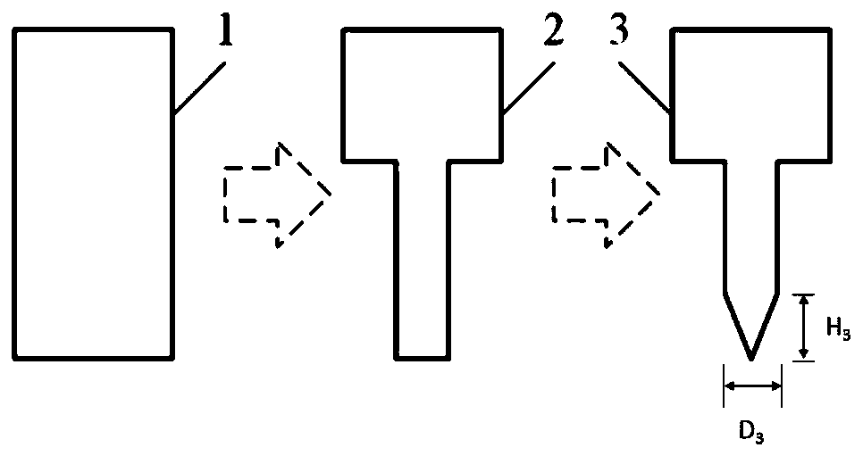
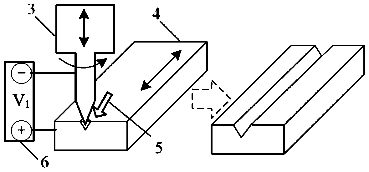
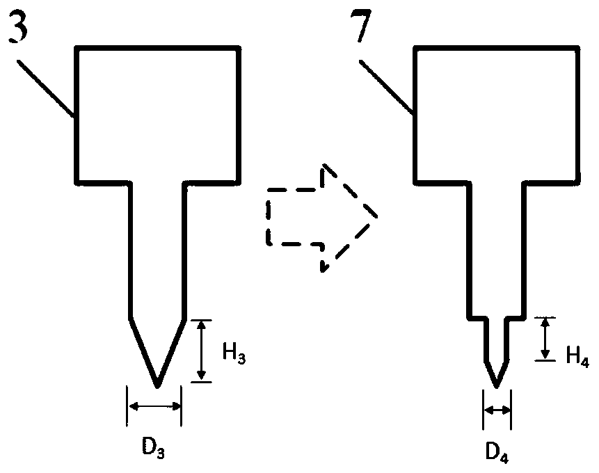
[0077] The invention aims to solve the high-quality manufacturing problem of the V-groove of the microfluidic chip injection mold. For V-shaped grooves with high hardness of injection mold material, small structure and sharp shape, and high surface quality requirements, the present invention provides a V-shaped linear groove and curved groove that can realize angles and smaller rounded corners in injection mold processing. method. The preparation method of the V-shaped groove of the microfluidic chip injection mold provided by the present invention includes providing a third micro-conical electrode with a conical tip to process the workpiece into the main body profile of the V-shaped groove, and then further forming the third micro-conical electrode The electrode is trimmed into a fourth tip conical electrode with a smaller cone height and angle, which is used to further modify the main body contour of the V-shaped groove to obtain a V-shaped groove with a smaller rounded corn...

Embodiment 1

[0109] The combined processing technology of a microfluidic chip injection mold core provided by the present invention will be described below with reference to the accompanying drawings and specific embodiments. This embodiment provides a method for preparing a V-shaped groove of an injection mold for a microfluidic chip, and the V-shaped groove is a linear groove structure. Among them, S136H mold steel is used as the workpiece material. S136H material is a plastic mold steel with excellent corrosion resistance. It has the characteristics of corrosion resistance, strain resistance, wear resistance, and easy to obtain a high-gloss surface. , the hardness can be tempered to 50HRC, and can be injected many times without deformation. After the mold made of this material is used for a long time, the surface of the mold can still maintain the original smooth state, and it does not need special protection when it is operated or stored in a humid environment.

[0110] The preparatio...

Embodiment 2

[0116] This embodiment provides a method for processing a V-shaped groove with an obtuse angle asymmetric structure curve, wherein the mechanism elements and workpiece materials indicated by the icons are the same as those in Embodiment 1. The specific steps and parameters are as follows:

[0117] (a) The first cylindrical electrode 1 made of tungsten and having a diameter of 500 μm is processed into a diameter D by using a wire electric discharge grinding (WEDG: Wire Electrical Discharge Grinding) method. 3 The second fine cylindrical electrode 2 is 164 μm. Utilize the plate electrode 8 that the material is copper to incline 30 °, by electrolytic back-copying the second micro cylindrical electrode 2, make the 3rd micro conical electrode 3 with 115 ° cone angle, refer to Figure 5 Shown, the cone height H 3 is 49 μm. The processing parameters of electrolytic reverse copying are: pulse voltage 8V, duty cycle 5: 5μs, electrolyte 1mol / L NaClO 3 And 0.01mol / L sodium citrate. ...


PUM

PropertyMeasurementUnit
Diameteraaaaaaaaaa
Diameteraaaaaaaaaa
Diameteraaaaaaaaaa

Abstract

The invention provides a preparation method and application of a V-shaped groove of a micro-fluidic chip injection mold and a preparation method of the micro-fluidic chip, and relates to the field ofmanufacturing of micro-fluidic chips. The preparation method of the V-shaped groove comprises the following steps of providing a third micro conical electrode with a conical tip to machine the workpiece to obtain a main body contour of the V-shaped groove, and then further trimming the third micro conical electrode into a fourth tip conical electrode with a smaller cone height and a smaller angleso as to further modify the body contour of the V-shaped groove to obtain the V-shaped groove with a smaller bottom end round angle. The preparation method solves the technical problem of lack of a high-quality process for manufacturing the V-shaped groove of the micro-fluidic chip injection mold in the prior art.

Description

technical field [0001] The invention relates to the field of microfluidic chip manufacturing, in particular to a method for preparing a V-shaped groove of an injection mold for a microfluidic chip and its application, and a method for preparing a microfluidic chip. Background technique [0002] Microfluidic chip technology integrates the basic operation units such as sample pretreatment, reaction, separation, and detection in the process of biological, chemical, and medical analysis into a chip with a size of several square centimeters, and runs through each operation link with a microchannel network. The whole process of analysis is completed automatically. Microfluidic chips have the characteristics of controllable liquid flow, small sample consumption, fast response, and easy integration. They are widely used in clinical diagnosis and disease screening fields such as hospital surgery, emergency, intensive care, and chronic disease prevention and treatment. Considering th...

Claims


Application Information

Patent Timeline
IPC IPC(8): B23H3/00B23H3/04B01L3/00B29C33/38
Inventor 李勇王志强钟昊孔全存刘国栋徐涛索轶平
Owner TIANJIN RES INST FOR ADVANCED EQUIP TSINGHUA UNIV
Learn More