
Solar cell with three-passivation layer structure, and preparation method of solar cell

A solar cell and passivation layer technology, which is applied in the manufacture of circuits, electrical components, and final products, can solve problems such as weak anti-PID performance and poor anti-PID ability on the back of PERC double-sided cells, and achieve enhanced anti-PID performance and enhanced Passivation effect, effect of improving battery efficiency

Pending Publication Date: 2019-06-14
TONGWEI SOLAR HEFEI +4
View PDF1 Cites 6 Cited by
  • Summary
  • Abstract
  • Description
  • Claims
  • Application Information

AI Technical Summary

Problems solved by technology

As the most cost-effective battery technology route at present, the large-scale application of PERC technology, like a butterfly wing, has instigated changes in the entire industry. At the same time, on the basis of PERC batteries, aluminum grid lines are used on the back, and the back structure of the battery can absorb reflection. Light and scattered light, and generate current, if the double-sided monocrystalline PERC cell is made into a double-glass module, it will have an additional power generation of 10%-30%. While the cell provides efficiency, the anti-PID performance is weak
[0003] In the prior art, the application number "200880124779.0" for manufacturing a solar cell with a surface passivation dielectric double layer and the corresponding solar cell, as well as other commonly used solar cells, have never been used in the process of use. The structure of depositing a silicon dioxide film layer on the front and back of the silicon substrate at the same time makes the produced PERC double-sided cells have poor anti-PID ability on the back.

Method used


Image

  • Solar cell with three-passivation layer structure, and preparation method of solar cell
  • Solar cell with three-passivation layer structure, and preparation method of solar cell

Examples


Embodiment Construction

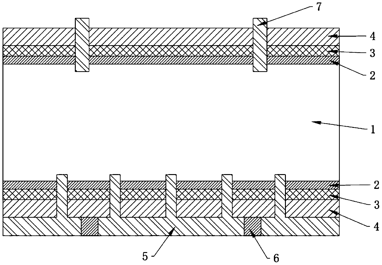
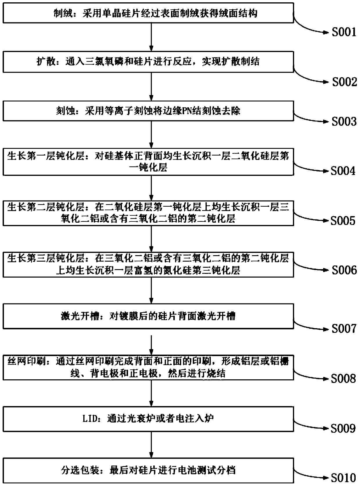
[0028] The following will clearly and completely describe the technical solutions in the embodiments of the present invention with reference to the accompanying drawings in the embodiments of the present invention. Obviously, the described embodiments are only some, not all, embodiments of the present invention. Based on the embodiments of the present invention, all other embodiments obtained by persons of ordinary skill in the art without making creative efforts belong to the protection scope of the present invention.

[0029] see Figures 1 to 2 , the present invention provides a technical solution:

[0030] A method for preparing a solar cell with a three-layer passivation layer structure, comprising the following steps:

[0031] Step S001, texturing: using monocrystalline silicon wafers to obtain a textured surface through surface texturing;

[0032] Step S002, Diffusion: Feed phosphorus oxychloride and silicon wafer to react to realize diffusion formation;

[0033] Ste...


PUM


Abstract

The invention discloses a solar cell with a three-passivation layer structure. The solar cell comprises a silicon substrate; a silicon dioxide layer, a first passivation layer, aluminum oxide or a second passivation layer containing the aluminum oxide and a third hydrogen-rich silicon nitride passivation layer are sequentially deposited on each of the front surface and the back surface of the silicon substrate; the third hydrogen-rich silicon nitride passivation layer located on the back surface of the silicon substrate is printed with an aluminum layer or an aluminum gate line and forms ohmiccontact with silicon through laser grooving, and the back surface is provided with a back electrode; and the third hydrogen-rich silicon nitride passivation layer located on the front surface of thesilicon substrate is provided with a positive electrode and an auxiliary gate line. The invention further discloses a preparation method of the solar cell with the three-passivation layer structure. The silicon dioxide film layer is grown and deposited on each of the front surface and the back surface of a silicon wafer, so that the passivation effects of the front and back surfaces are well enhanced, the anti-PID performance of the cell is enhanced, and the cell efficiency can be effectively improved.

Description

technical field [0001] The invention relates to the technical field of photovoltaic cells, in particular to a solar cell with a three-layer passivation layer structure and a preparation method thereof. Background technique [0002] PERC technology has obvious performance and cost advantages, and its power generation capacity and broad application prospects are generally recognized in the industry. As the most cost-effective battery technology route at present, the large-scale application of PERC technology, like a butterfly wing, has instigated changes in the entire industry. At the same time, on the basis of PERC batteries, aluminum grid lines are used on the back, and the back structure of the battery can absorb reflection. Light and scattered light generate current. If the bifacial monocrystalline PERC cell is made into a double-glass module, it will have an additional power generation of 10%-30%. While the cell provides efficiency, the anti-PID performance is weak. [0...

Claims


Application Information

Patent Timeline
Patent Type & Authority Applications(China)
IPC IPC(8): H01L31/18H01L31/0216
CPCY02P70/50
Inventor 尹丙伟张忠文吴俊旻张鹏杨蕾余波王岚
Owner TONGWEI SOLAR HEFEI
Learn More