
Equipment inhibiting generation of dioxin in incineration flue gas and use method of equipment

A technology for generating equipment and flue gas, which is applied in separation methods, chemical instruments and methods, and separation of dispersed particles, etc. It can solve the problems of increasing the operation consumption of back-end induced draft fans, collection and transportation of small micro-powder, collection and transportation of micro-powder, etc. problems, to achieve a good effect of comprehensive utilization of resources, reduce acid gas content, and inhibit the formation of dioxins

Inactive Publication Date: 2019-06-21
上海环保工程成套有限公司
View PDF7 Cites 11 Cited by
  • Summary
  • Abstract
  • Description
  • Claims
  • Application Information

AI Technical Summary

Problems solved by technology

The disadvantage of this kind of process is: the price of using ammonium dihydrogen phosphate as the inhibitor is relatively expensive, which will inevitably increase the operating cost of the device
Although this process grinds the inhibitor, it does not describe the problem of fine powder collection and transportation generated during the grinding process, that is, the problem of fine powder collection and transportation with small particle size is one of the core problems of this technology
Secondly, the ground fine powder, activated carbon and flue gas cannot ensure sufficient reaction in the reaction tank only through the diversion structure, because the ground fine powder is prone to sticking to the wall
Finally, introducing the flue gas into the reaction tank with a new cyclone bag filter will inevitably increase the resistance loss of the flue gas, thereby increasing the operating consumption of the rear-end induced draft fan

Method used


Image

  • Equipment inhibiting generation of dioxin in incineration flue gas and use method of equipment
  • Equipment inhibiting generation of dioxin in incineration flue gas and use method of equipment
  • Equipment inhibiting generation of dioxin in incineration flue gas and use method of equipment

Examples


Embodiment 1

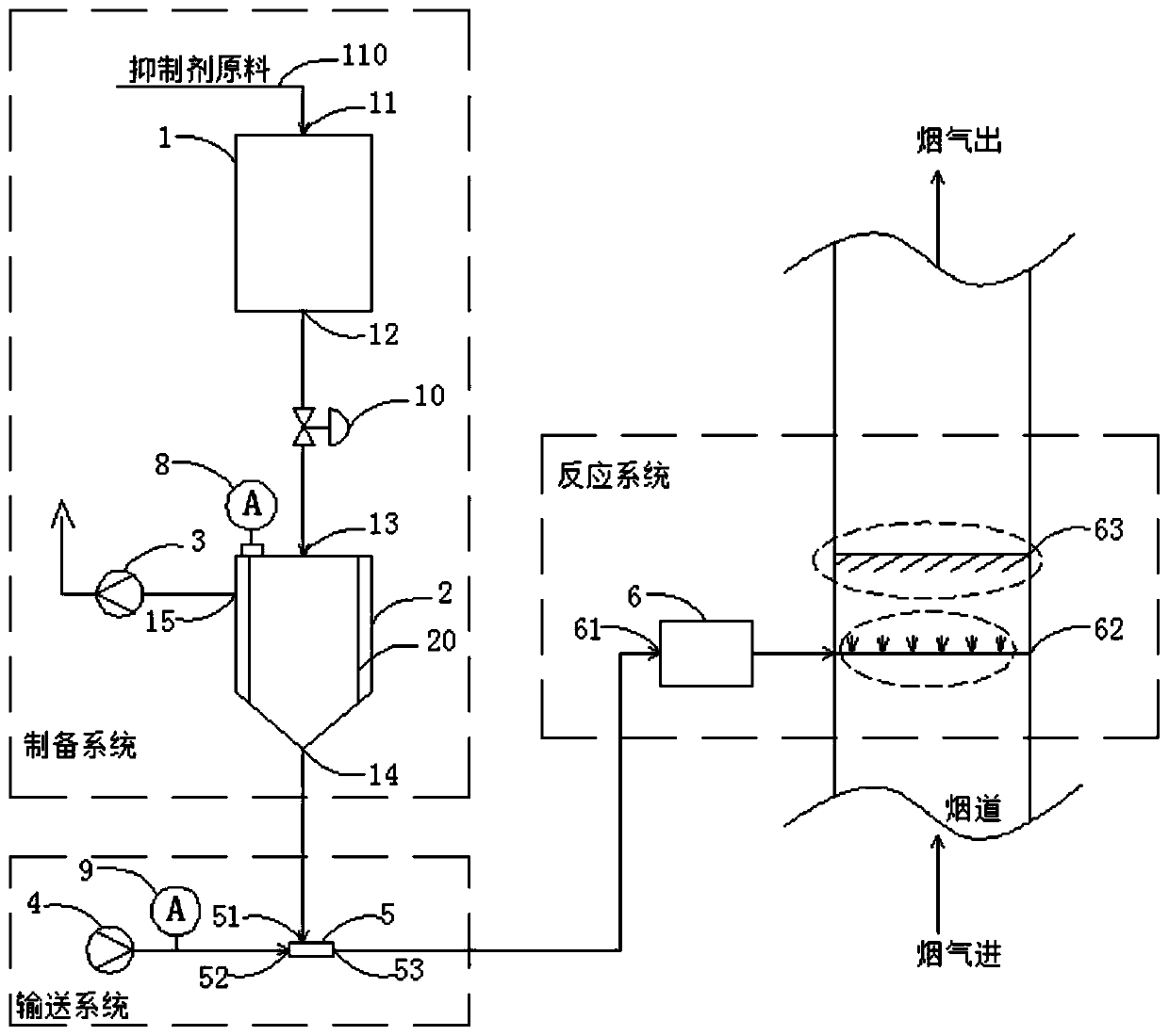
[0032] Such as figure 1 The shown device for suppressing the generation of dioxin in the flue gas of incineration includes a micropowder inhibitor preparation system, a micropowder inhibitor delivery system and a reaction system.

[0033] Adopting a waste incinerator in the form of a circulating fluidized bed with a processing capacity of 400 tons per day, the flue gas volume under stable operating conditions reaches 250,000 Nm per hour. After the flue gas passes through the economizer and the air preheater to recover the heat of the flue gas, the flue gas enters the flue gas purification process section, and the purified flue gas meets the standard and is discharged. The device for suppressing the generation of dioxins in the flue gas of incineration is installed downstream of the economizer, and is used to suppress the re-formation of dioxins in the incineration process and flue gas cooling process without affecting the recovery of flue gas heat.

[0034] The micropowder in...

Embodiment 2

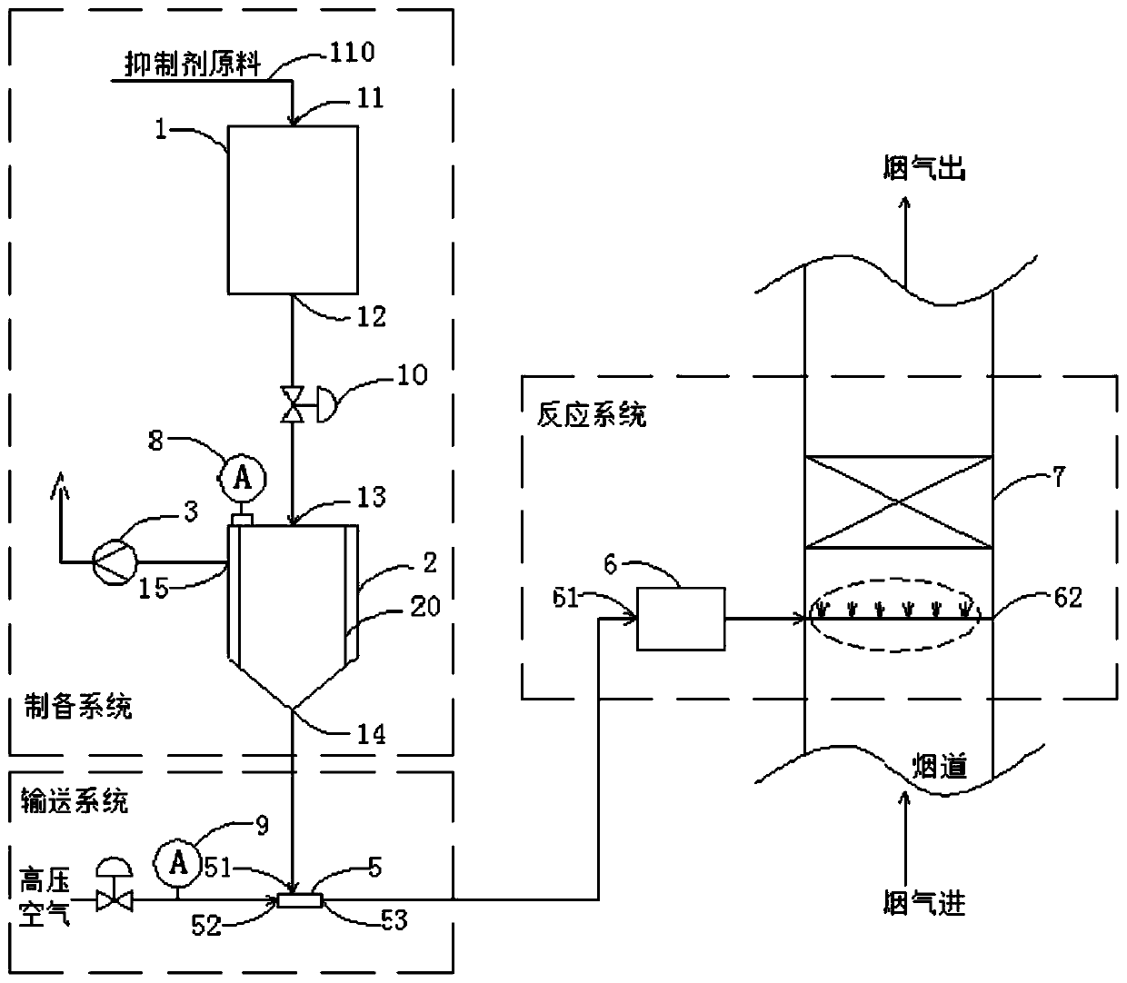
[0048] Such as figure 2 Compared with Example 1, the shown device for suppressing the generation of dioxins in the flue gas of incineration: the Roots blower 4 is changed to high-pressure air and valves are added; when the deflector 63 is not installed, the packing is added Layer 7, other structures and process conditions are the same as those in Embodiment 1.

[0049] The high-pressure air comes from the utility part of the factory, and the delivery gas inlet 52 of the gas-solid mixing device 5 is connected to the utility pipeline. control.

[0050] A layer of filler layer 7 is arranged in the reaction system. The filler material of the filler layer 7 is inorganic ceramics, the opening ratio of which is about 85%, and the thickness of the filler layer 7 is 100mm. The micropowder inhibitor is sprayed into the flue through the gas-solid injection device 62, fully mixed and reacted with the flue gas, flows through the packing layer 7, and then reduces the concentration of chl...

Embodiment 3

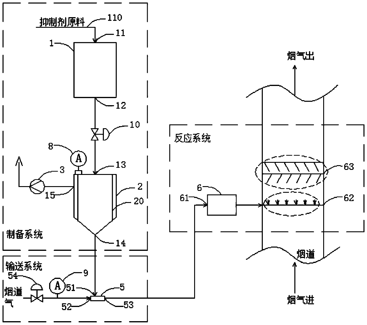
[0054] Such as image 3 Compared with Example 1, the shown device for suppressing the generation of dioxin in the flue gas of incineration: the Roots blower 4 is changed to flue gas and a regulating valve 54 is added, and two layers of deflectors 63 with different angles are installed , other structures and processing conditions are the same as in Example 1.

[0055] The flue gas of the micropowder inhibitor conveying system comes from the gas in the flue that has been pressurized after the reaction of the sprayed inhibitor. The conveying gas inlet 52 of the gas-solid mixing device 5 is connected to the flue gas pipeline. In order to ensure the stability of the process operation, connect A regulating valve 54 is added on the official road, and the regulating valve 54 is controlled by the measuring instrument 9 .

[0056] Two layers of deflectors 63 are set in the reaction system. In order to meet the ideal flow state of the flue gas in the flue, a layer of deflectors 63 is ad...


PUM


Abstract

The invention relates to equipment inhibiting generation of dioxin in incineration flue gas and a use method of the equipment. The equipment comprises a micropowder inhibitor preparation system, a micropowder inhibitor conveying system and a reaction system, wherein the micropowder inhibitor preparation system comprises a micron-sized solid inhibitor production device and a micropowder inhibitor storage tank that are sequentially connected; the micropowder inhibitor storage tank is connected with a gas extractor; the micropowder inhibitor conveying system comprises a pneumatic conveying sourceand a gas-solid mixing device that are sequentially connected; a feed port of the gas-solid mixing device is connected with a discharge port of the micropowder inhibitor storage tank; the reaction system comprises a gas-solid mixing and distributing device and a gas-solid spray device that are sequentially connected; a feed port of the gas-solid mixing and distributing device is connected with adischarge port of the gas-solid mixing device; and the gas-solid spray device is arranged in a flue gas pipeline and performs distribution through the gas-solid mixing and distributing device. The equipment can improve an inhibition effect on the generation of dioxin in the incineration flue gas and reduce influence on conveying of the incineration flue gas.

Description

technical field [0001] The invention belongs to the technical field of incineration flue gas treatment, in particular to a device for suppressing the generation of dioxin in incineration flue gas and a method for using the same. Background technique [0002] The solid waste disposal with incineration as the core is the most thorough, fast and economical method. The incineration of garbage, sludge and hazardous waste is one of the main methods for urban production and domestic waste treatment; in addition, with environmental protection requirements and Relevant thermal power industry policies have been promulgated one after another, and the thermal power industry has gradually increased sludge blending projects, making power generation companies not only transform into "policy" power plants, but also help to increase the survival value of power plants. However, the inadequacy of incineration technology is mainly reflected in the existence of toxic and harmful substances in th...

Claims


Application Information

Patent Timeline
Patent Type & Authority Applications(China)
IPC IPC(8): B01D53/83B01D53/40B01D53/68
Inventor 龙宝玉王少波黄华李畅宇刘万聚
Owner 上海环保工程成套有限公司
Learn More