
Smoke gas composite tube waste heat recovery device

A waste heat recovery device and composite tube technology, applied in indirect heat exchangers, heat exchanger types, climate sustainability, etc., can solve the problems of environmental pollution, production shutdown losses, low efficiency, etc., and achieve high heat exchange efficiency and savings. Energy cost, effect of increased temperature

Inactive Publication Date: 2019-06-21
厦门高谱科技有限公司
View PDF5 Cites 0 Cited by
  • Summary
  • Abstract
  • Description
  • Claims
  • Application Information

AI Technical Summary

Problems solved by technology

[0002] Existing ovens or kilns in the automotive industry, glass industry, metallurgical industry, carbon industry, ceramics industry, food industry, textile industry, cement industry, chemical industry, etc. have low efficiency for waste heat recovery and utilization of flue gas from kilns, for example, automobile During the production process of the painting workshop, the paint on the surface of the car body needs to be baked and dried in the drying room, and the drying room will generate a large amount of organic waste gas. Discharge after environmental protection requirements
However, the temperature of the flue gas emitted by the incinerator or oven is between 180-250°C, and some are even higher
At present, they are directly discharged, causing energy waste, and the flue gas with too high temperature directly enters the atmosphere, which will indirectly cause environmental pollution. In fact, this part of heat energy can be recycled; moreover, the existing conventional heat exchange equipment is generally Through a heat transfer tube (single tube) for heat exchange, the hot and cold fluids flow through both sides of the inner and outer walls of the heat transfer tube respectively. If the tube wall leaks, it will cause production shutdown losses

Method used


Image

  • Smoke gas composite tube waste heat recovery device
  • Smoke gas composite tube waste heat recovery device
  • Smoke gas composite tube waste heat recovery device

Examples


Embodiment 1

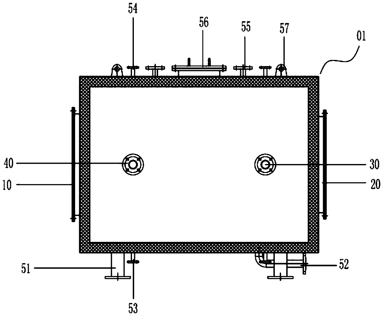
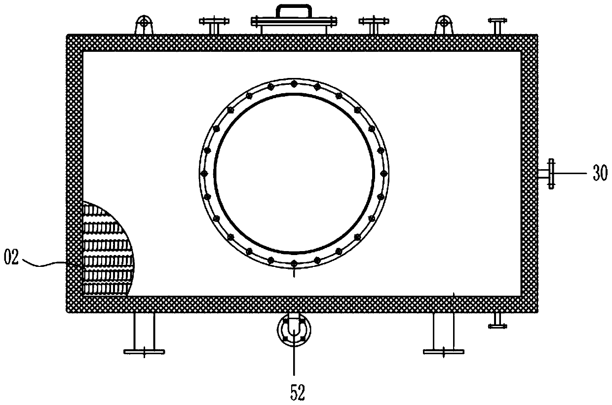
[0029] see Figure 1 to Figure 2 , is a flue gas composite pipe waste heat recovery device as Embodiment 1 of the present invention, which is mainly used for waste heat recovery and utilization of high-temperature flue gas discharged from automobile coating ovens. A plurality of heat exchange tubes, the outer casing is provided with a smoke inlet, a smoke outlet, a liquid inlet and a liquid outlet, the liquid inlet and the liquid outlet are arranged at both ends of the outer casing, and several heat exchange tubes are arranged side by side set, and the axis of the heat exchange tube is perpendicular to the axis of the liquid inlet and the liquid outlet. Specifically, the inside of the outer shell is covered with heat exchange tubes, and the heat exchange tubes are arranged in an array; at the same time, the flue gas passes through the smoke inlet It enters, passes through the heat exchange tube, and is discharged from the smoke outlet, while the circulating liquid enters throu...

Embodiment 2

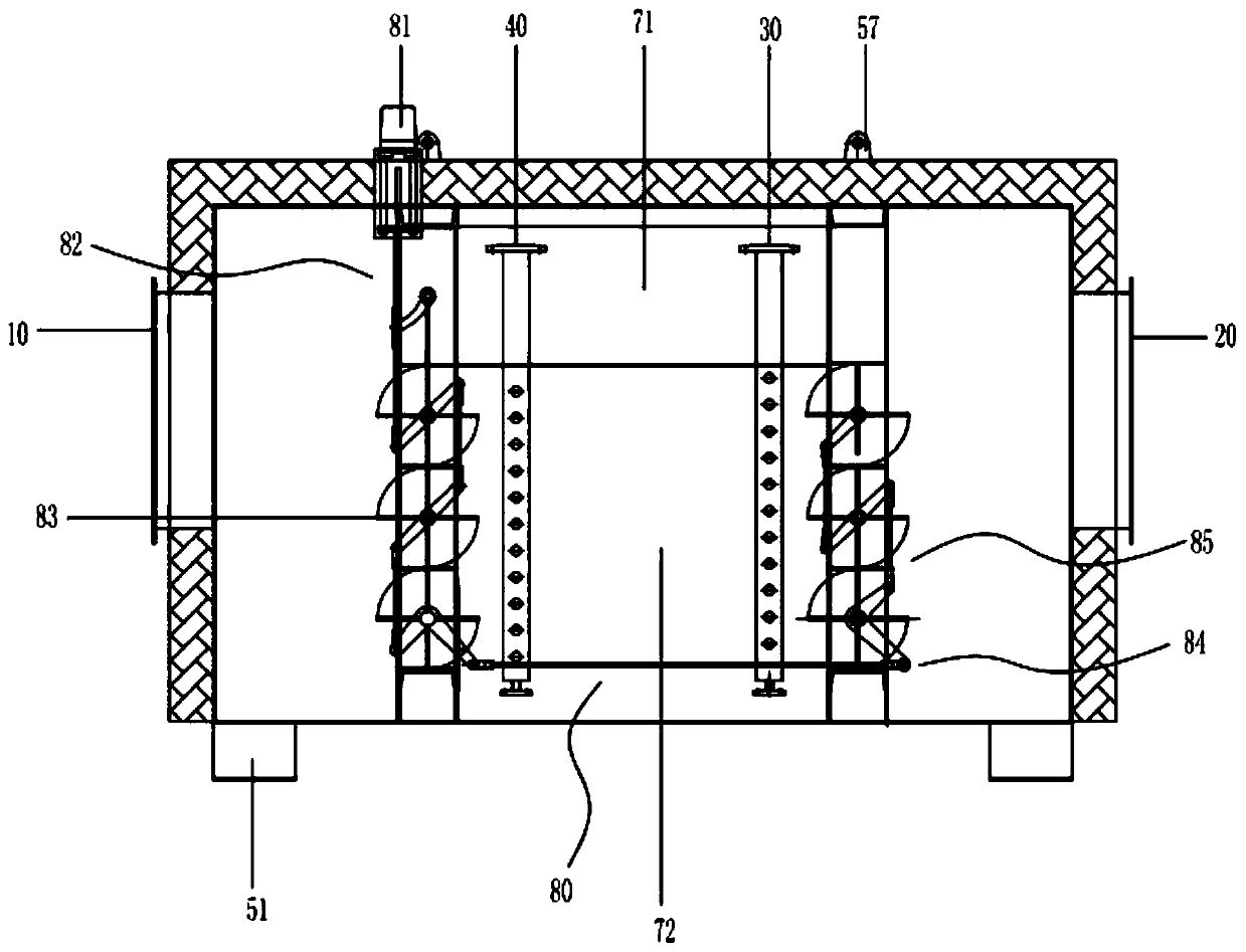
[0034] see Figure 3 to Figure 4 , is a flue gas composite pipe waste heat recovery device as Embodiment 1 of the present invention, which is mainly used for waste heat recovery and utilization of high-temperature flue gas discharged from an automobile coating incinerator. A plurality of heat exchange tubes, the outer casing is provided with a smoke inlet, a smoke outlet, a liquid inlet and a liquid outlet, the liquid inlet and the liquid outlet are arranged at both ends of the outer casing, and several heat exchange tubes are arranged side by side set, and the axis of the heat exchange tube is set perpendicular to the axis of the liquid inlet and the liquid outlet. Specifically, a first channel and a second channel are arranged inside the outer casing, and the inside of the second channel is covered with heat exchange tubes. And the heat exchange tubes are arranged in an array; when heat needs to be recovered, the second channel can be opened directly; at the same time, the f...


PUM


Abstract

The invention provides a smoke gas composite tube waste heat recovery device. The smoke gas composite tube waste heat recovery device comprises an outer shell body and a plurality of heat exchanger tubes arranged in the outer shell body, a smoke inlet, a smoke outlet, a liquid inlet and a liquid outlet are formed in the outer shell body, the liquid inlet and the liquid outlet are formed in the twoends of the outer shell body, the heat exchanger tubes are arranged side by side, and the axes of the heat exchanger tubes are perpendicular to the axes of the liquid inlet and liquid outlet; the heat exchanger tubes comprise outer tubes and inner tubes, the outer tubes and the inner tubes are concentric tubes, an enclosed space is formed between the outer tubes and the inner tubes, thin-walled tubes are fixedly arranged in the enclosed space, the thin-walled tubes and the inner tubes are concentric tubes, and working liquid is arranged in the enclosed space and circularly flows along the inner sides and the outer sides of the concentric tubes; and the heat exchanger tubes are sequentially connected in an end-to-end mode, the starting ends of the inner tubes after connection are connectedwith the liquid inlet, and the tail ends of the inner tubes are connected with the liquid outlet.

Description

technical field [0001] The invention relates to the technical field of waste heat recovery devices, in particular to a flue gas composite pipe waste heat recovery device. Background technique [0002] Existing ovens or kilns in the automotive industry, glass industry, metallurgical industry, carbon industry, ceramics industry, food industry, textile industry, cement industry, chemical industry, etc. have low efficiency for waste heat recovery and utilization of flue gas from kilns, for example, automobile During the production process of the painting workshop, the paint on the surface of the car body needs to be baked and dried in the drying room, and the drying room will generate a large amount of organic waste gas. Discharge after meeting environmental protection requirements. However, the temperature of the flue gas discharged from the incinerator or oven is between 180-250°C, and some are even higher. At present, they are directly discharged, causing energy waste, and ...

Claims


Application Information

Patent Timeline
IPC IPC(8): F28D7/16F28D7/10F23J15/06
CPCY02E20/30
Inventor 苏海军
Owner 厦门高谱科技有限公司
Learn More