Distance error correction system for laser radar

A technology of laser radar and compensation system, which is applied in the field of compensation system, can solve problems affecting measurement results, signal strength fluctuation, signal broadening, etc., achieve good stability and repeatability, reduce signal noise, and enhance stability

Inactive Publication Date: 2019-06-21
合肥嘉东光学股份有限公司
View PDF10 Cites 5 Cited by
  • Summary
  • Abstract
  • Description
  • Claims
  • Application Information

AI Technical Summary

Problems solved by technology

[0003] Because of changes in the reflectivity of objects or changes in the measurement distance and other factors, the signal amplitude measured by the photodetector changes. Especially for lidar with a relatively large measurement range, the signal strength measured at short and long distances is bound to be very different. Large fluctuations, which will cause the rising edge of the signal waveform output by the photodetector to be distorted, and the signal will be broadened, which will affect the measurement result of the stop time

Method used


Image

  • Distance error correction system for laser radar
  • Distance error correction system for laser radar
  • Distance error correction system for laser radar

Examples


Embodiment 1

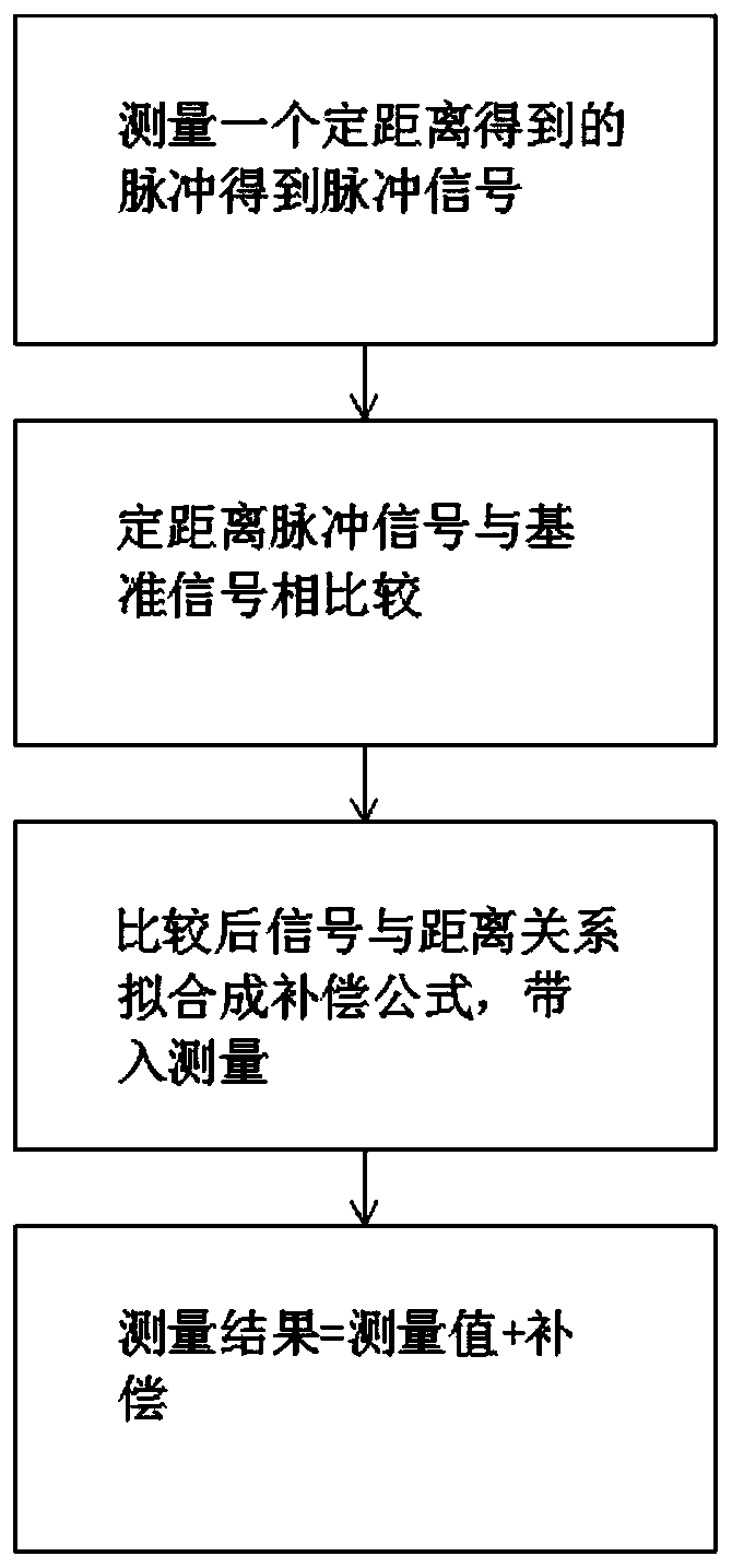
[0036] Embodiment 1: as figure 1 Be the flow chart of the steps of the whole compensation system of the present invention in

[0037] The laser radar is placed in a fixed position, adjust the left and right position and pitch position of the emitting laser point, and keep the laser beam and the measurement target at the discovered position, so that an accurate distance value can be measured. If the laser beam is offset, the measured distance and the actual distance will have a plane or space angle θ. Δ=L-Lsinθ, Δ is the measurement distance error

[0038] L is the actual measurement distance

[0039] θ is the angle between the laser beam and the normal of the measurement target

[0040] The tooling for placing the lidar and measuring objects can adjust the left and right rotation angles and pitch angles.

[0041] The laser radar and the measurement target are placed on an automated test guide rail, which can automatically walk to the required measurement distance, and the ...

Embodiment 2

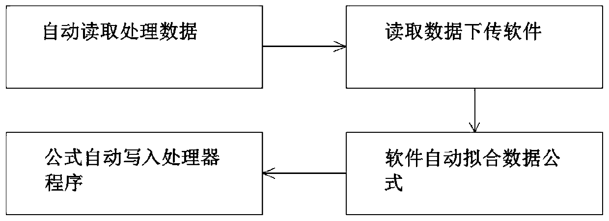
[0044] Embodiment 2: as figure 2 In the middle is a flow chart of key data receiving and receiving and data fitting of the present invention:

[0045] The data is read multiple times, the average value of all data is calculated, and a threshold range is set. If the value is greater than the threshold range, it will be treated as abnormal data, and then the average value will be calculated and sent to the data processing software as valid data after removing the abnormal data.

[0046] The test software obtains the measured echo signal characteristic values ​​B1, B2, B3...Bn

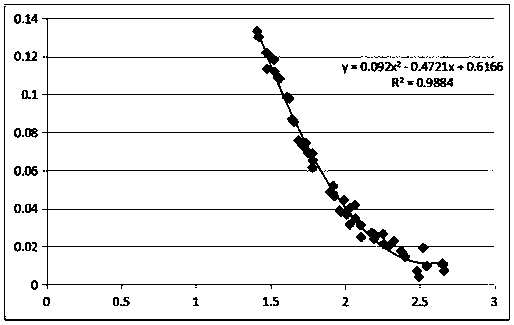
[0047] The automatic test guide rails are set with fixed distances L1, L2, L3...Ln, the obtained time t1, t2, t3...tn, the obtained time is calculated by the formula (d=1 / 2ct) to obtain the distance d1, d2, d3...dn , when calculating the error value Δ(Δ=D-L) between the measured distance and the real distance.

[0048] The figure shows the polynomial curve fitted between the measurement error Δ and the...

Embodiment 3

[0054] Embodiment 3: as image 3 The middle is a schematic diagram of a TOF-based miniaturized coaxial lidar system:


PUM


Abstract

The invention relates to an error correction method for the measuring distance accuracy of a laser radar by a laser radar echo signal and distance. The method comprise the following steps that: a laser radar emits a light pulse and the light pulse is detected and received by a photoelectric detector to obtain a Gaussian signal; a measuring error is corrected according to different signal strengthinformation obtained by different distances; and since the object measuring distances are different, the surface reflectivities of the measured objects are different and the tilt angles of the measures object are different, so that the energy change of the light pulse returning to the optical detector after irradiation on the object surface is affected. A problem that various factors, causing themeasured return power changes, of the object change in the laser radar measurement process and thus the accuracy of the measurement result is affected is solved. With the correction system, the measurement result is closer to the real distance and the measurement accuracy is improved.

Description

technical field [0001] The invention relates to a laser radar system, in particular to a compensation system for the laser radar to compensate measurement errors caused by factors such as different distances, different reflectivities, and different reflective surfaces. Background technique [0002] The principle of lidar ranging is to calculate the time elapsed by a pulse optical path multiplied by the speed of light, record a start time when the laser is emitted, and record the stop time when the light detector receives the signal. The returned optical signal outputs an analog signal after passing through the optical detector. The TDC circuit needs to perform time identification. The time identification can be roughly divided into leading edge threshold detection, constant ratio timing detection, zero-crossing detection, peak detection, etc. There are more or less detection errors in these detection methods, which are often referred to as "walking errors". [0003] Because...

Claims


Application Information

Patent Timeline
Patent Type & Authority Applications(China)
IPC IPC(8): G01S7/497
Inventor 胡卫东王冬徐跃明
Owner 合肥嘉东光学股份有限公司
Why Eureka
Try Eureka