Embedded SCR flue gas denitration reactor and method in waste heat boiler for cement kiln flue gas denitration

A technology of denitration reactor and waste heat boiler, which is applied in chemical instruments and methods, separation methods, and dispersed particle separation, etc., can solve the problems of difficult reconstruction of SCR reactors, large system pressure loss, large resistance loss, etc., so as to avoid the system The effect of large pressure loss, small system pressure loss and large temperature drop loss

Pending Publication Date: 2019-07-09
浙江省环境科技有限公司
View PDF2 Cites 3 Cited by
  • Summary
  • Abstract
  • Description
  • Claims
  • Application Information

AI Technical Summary

Problems solved by technology

[0006] Aiming at the problems of conventional independent external SCR reactors such as difficulty in retrofitting, large temperature drop, and large resistance loss, the invention provides a built-in SCR flue gas denitration reactor and flue gas denitrification method in the waste heat boiler, which directly transforms the waste heat boiler appropriately. Finally, the SCR reactor is embedded in the waste heat boiler, and the technical method of embedding the SCR flue gas denitrification reactor in the waste heat boiler is used to change the conventional thinking. The SCR denitrification reactor is often installed independently, and the system pressure is avoided while adding the SCR reactor. Large loss, long process, large temperature drop, etc.

Method used


Image

  • Embedded SCR flue gas denitration reactor and method in waste heat boiler for cement kiln flue gas denitration
  • Embedded SCR flue gas denitration reactor and method in waste heat boiler for cement kiln flue gas denitration

Examples


Embodiment 1

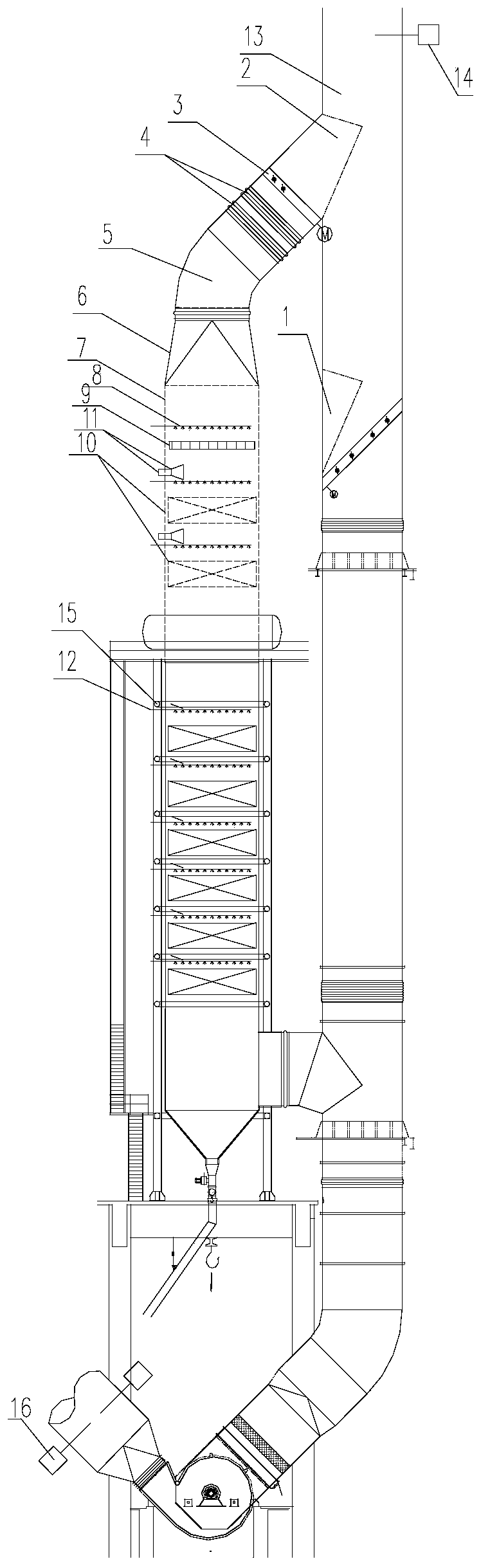
[0055] SCR denitrification test device for cement kilns with a daily output of 2,500 tons, with a flue gas volume of 250,000Nm 3 / h, inlet flue gas temperature 350℃±20℃, dust content 30-100g / m 3 , NOx initial concentration 280-1200mg / m 3 (The upstream of the SCR denitrification reactor has been equipped with SNCR denitrification devices. If the upstream SNCR denitrification devices are not put into operation, the initial concentration will be as high as 700-1200mg / m 3 , after the upstream SNCR denitrification device is put into operation, the minimum NOx emission concentration can be controlled at 200mg / m 3 , design NOx concentration after denitrification 3 , ammonia escape concentration 3 .

[0056] see attached figure 1 , lift the upper part of the waste heat boiler to expand the capacity, and raise the opening point of the flue by 10m. The original flue parts inlet part 2, baffle door 3, expansion joint 4, shrimp bend 5, and square and round joint 6 are directly used for...


PUM


Abstract

The invention discloses an embedded SCR flue gas denitration reactor and method in waste heat boiler for cement kiln flue gas denitration. The device comprises a waste heat boiler, a top smoke inlet of the waste heat boiler is connected into a vertical waste heat boiler inlet flue, the top end of the waste heat boiler inlet flue is connected with a cement kiln tail preheater C1-level cyclone outlet, and a plurality of layers of horizontal heat exchange pipes are arranged in the waste heat boiler; a vertical expansion section is additionally arranged between the uppermost horizontal heat exchange pipe in the waste heat boiler and the top flue gas inlet, and a plurality of catalyst layers are arranged in the vertical expansion section and the waste heat boiler body section at intervals in the flue gas flow direction; a soot blower is correspondingly arranged above each catalyst layer; a rectifier is arranged above the top catalyst layer; and an ammonia spraying device is arranged above the rectifier. The waste heat boiler is directly and properly transformed, a conventional idea that an SCR denitration reactor is usually and independently arranged is changed, and the problems that the system pressure loss is large, the flow path is long, the temperature drop is large and the like are avoided while the SCR reactor is additionally arranged.

Description

technical field [0001] The invention relates to an industrial kiln flue gas nitrogen oxide treatment technology, in particular to a selective catalytic reduction denitrification technology (Selective Catalytic Reduction, SCR) applied to cement clinker production line kiln tail high dust flue gas. Background technique [0002] There are three main types of NOx control technologies for cement kilns: Low NOx burner (LNB), Selective Non-Catalytic Reduction (SNCR) and Selective Catalytic Reduction (Selective Catalytic Reduction) technologies. Reduction, SCR). According to the denitrification efficiency from low to high, the low nitrogen combustion technology is about 10%-30%, the SNCR denitrification technology is about 50%-70%, and the SCR denitrification is as high as 80-90%. [0003] Conventional SCR denitrification technology is independent of the original production system. After reasonable modification of the flue, an SCR reactor loaded with catalyst is installed in series...

Claims


Application Information

Patent Timeline
Patent Type & Authority Applications(China)
IPC IPC(8): B01D53/90B01D53/56
CPCB01D53/8631B01D53/90
Inventor 韦彦斐周荣彭兴华詹杰陈幼荣
Owner 浙江省环境科技有限公司
Why Eureka
Try Eureka