
System for cement SCR denitration and tail gas treatment

A technology for exhaust gas treatment and denitration, which is applied in the field of industrial flue gas treatment, can solve the problems of poisoning temperature, high dust concentration, catalyst blockage, etc., and achieve the effects of reducing equipment height, ammonia escape, and operating costs.

Inactive Publication Date: 2019-07-12
XIAN XIKUANG ENVIRONMENTAL PROTECTION
View PDF6 Cites 1 Cited by
  • Summary
  • Abstract
  • Description
  • Claims
  • Application Information

AI Technical Summary

Problems solved by technology

[0002] SCR denitrification technology has been maturely applied in my country's power industry and can stabilize the long-term emission of nitrogen oxides to 50mg / Nm 3 In the following, to achieve ultra-low emissions of nitrogen oxides in cement kilns, SCR denitrification technology is the only choice at this stage. However, SCR denitrification in the cement industry is faced with high dust concentration and high content of alkali metal oxides such as calcium oxide in dust, which can easily cause catalyst blockage and damage. Due to the characteristics of poisoning and low working temperature, copying the SCR denitrification device in the power industry has a relatively large risk; and the domestic cement industry has not yet had any performance in SCR denitrification. How to combine the characteristics of cement technology to formulate a technology that is suitable for the cement industry both technically and economically. SCR denitrification technology is particularly important

Method used


Image

  • System for cement SCR denitration and tail gas treatment
  • System for cement SCR denitration and tail gas treatment
  • System for cement SCR denitration and tail gas treatment

Examples


Embodiment Construction

[0025] The following will clearly and completely describe the technical solutions in the embodiments of the present invention with reference to the accompanying drawings in the embodiments of the present invention. Obviously, the described embodiments are only some, not all, embodiments of the present invention. Based on the embodiments of the present invention, all other embodiments obtained by persons of ordinary skill in the art without making creative efforts belong to the protection scope of the present invention.

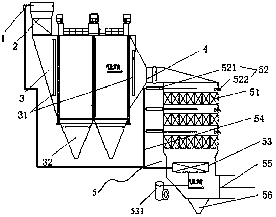
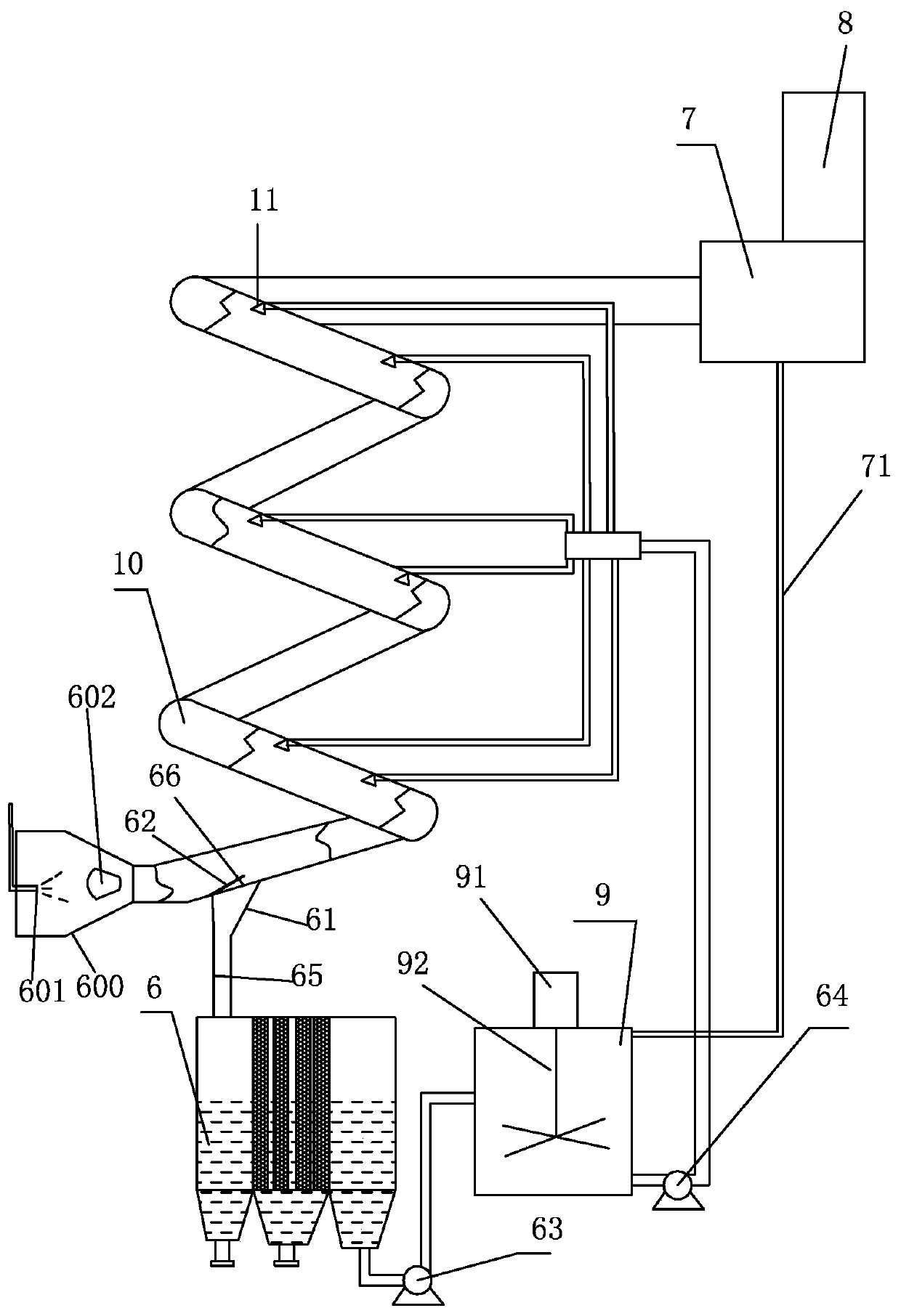
[0026] As shown in the figure, a cement SCR denitrification and tail gas treatment system includes a dual-fluid spray gun 1, an intake flue 2, a high-temperature electrostatic precipitator 3, an outlet flue 4, and a denitrification reactor 5. The dual-fluid spray gun 1 is arranged on the intake flue 2, and the intake flue 2 is connected to the top inlet of the high-temperature electrostatic precipitator 3, and at least one layer of air distribution plate 31 for...


PUM


Abstract

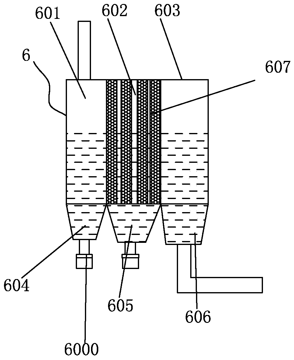
A system for cement SCR denitration and tail gas treatment comprises an air inlet flue, a high-temperature electrostatic precipitator, an air outlet flue and a denitration reactor. The system is characterized in that the air inlet flue is connected with the top inlet of the high-temperature electrostatic precipitator; the bottom of the high-temperature electrostatic precipitator is provided with multiple dust-remover ash buckets; the lateral part of the high-temperature electrostatic precipitator is provided with an air outlet, which is connected to the denitration reactor through the air outlet flue; the denitration reactor comprises a multi-layer catalyst ceramic material, multiple soot blowers, a heat exchanger and a compressed air conveying pipeline; and the sooth blower comprises a rake soot blower and an acoustic soot blower, which are respectively arranged at two sides above the catalyst ceramic material. The nitrogen removal efficiency is enhanced, consumption of ammonia wateris reduced, and ammonia escape is decreased; the process is optimized, the ammonia water evaporation procedure is saved, and the cost and operating expense are lowered. By the adoption of a spiral washing device for desulphurization of tail gas, absorptivity of sulfides in the tail gas is improved.

Description

technical field [0001] The invention relates to the technical field of industrial flue gas treatment, in particular to a cement SCR denitrification and tail gas treatment system. Background technique [0002] SCR denitrification technology has been maturely applied in my country's power industry and can stabilize the long-term emission of nitrogen oxides to 50mg / Nm 3 In the following, to achieve ultra-low emissions of nitrogen oxides in cement kilns, SCR denitrification technology is the only choice at this stage. However, SCR denitrification in the cement industry is faced with high dust concentration and high content of alkali metal oxides such as calcium oxide in dust, which can easily cause catalyst blockage and damage. Due to the characteristics of poisoning and low working temperature, copying the SCR denitrification device in the power industry has a relatively large risk; and the domestic cement industry has not yet had any performance in SCR denitrification. How to ...

Claims


Application Information

Patent Timeline
Patent Type & Authority Applications(China)
IPC IPC(8): B01D53/75B01D53/76B01D53/78B01D53/86B01D53/90B03C3/00B01D53/50B01D53/56
CPCB01D53/504B01D53/56B01D53/75B01D53/76B01D53/78B01D53/8631B01D53/90B01D2258/0233B01D2258/0283B03C3/00
Inventor 陈贵福雷华李凌霄
Owner XIAN XIKUANG ENVIRONMENTAL PROTECTION
Learn More