Waveguide pressure sensor based on M-Z structure and detection method

A pressure sensor, M-Z technology, applied in fluid pressure measurement using optical methods, measurement of the change force of the optical properties of the material when it is stressed, and instruments, etc., can solve the problem of limited range, etc., to achieve large range, high Measurement accuracy, strong pressure resistance effect

Inactive Publication Date: 2019-07-16
SHANDONG UNIV
View PDF6 Cites 3 Cited by
  • Summary
  • Abstract
  • Description
  • Claims
  • Application Information

AI Technical Summary

Problems solved by technology

[0004] In the prior art, for example, traditional M-Z structure interference optical pressure sensors are mostly based on force-sensitive films, and the measurement range is limited by the fracture pressure of the film, so the ra

Method used


Image

  • Waveguide pressure sensor based on M-Z structure and detection method
  • Waveguide pressure sensor based on M-Z structure and detection method
  • Waveguide pressure sensor based on M-Z structure and detection method

Examples


Embodiment 1

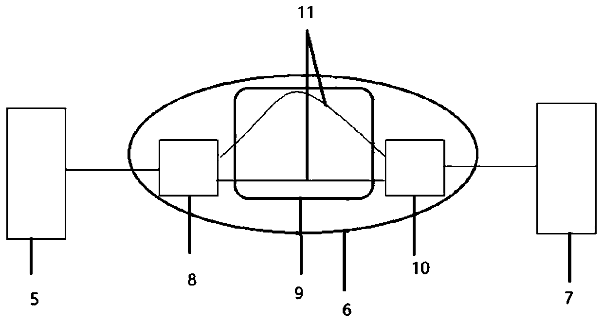
[0044] A waveguide pressure sensor based on M-Z structure, such as figure 1 As shown, it includes a single-wavelength light source 5, an M-Z structure 6 and an optical power meter 7; the single-wavelength light source 5, the M-Z structure 6 and the optical power meter 7 are connected in sequence, and the M-Z structure 6 includes an input coupler 8 connected in sequence, consisting of two different lengths The pressure sensing region 9 and the output coupler 10 are composed of a single-mode waveguide 11 . like Figure 6 As shown, one of the two single-mode waveguides 11 is linear and the other is sinusoidal, and the length difference ΔL between the two single-mode waveguides 11 is 0-10 mm. Since the sinusoidal shape is easy to design in the optical simulation software and export the pattern, it can be used as the preferred type.

[0045] The single-mode waveguide 11 is a strip waveguide or a ridge waveguide, the width of the single-mode waveguide 11 is 0.5-8 μm, and the thickne...

Embodiment 2

[0049] According to the waveguide pressure sensor based on the M-Z structure provided in Embodiment 1, the difference is that:

[0050] Such as Figure 7 As shown, among the two single-mode waveguides 11, one is linear, and the other is arc spliced, and the length difference between the two single-mode waveguides 11 is 0-50 mm. When ΔL is 50mm, the sensor range is 2MPa.

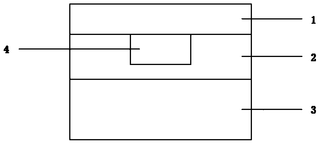
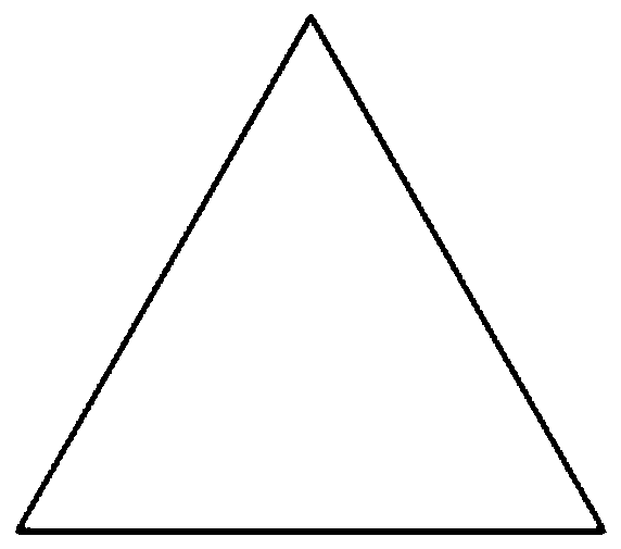
[0051] The upper part of the two single-mode waveguides 11 with different lengths in the pressure sensing area 9 is provided with a force equalization module, such as image 3 and Figure 4 As shown, the shape of the uniform force module is a regular pyramid. The bottom surface of the force equalizing module is arranged on the pressure sensing area 9 , and the bottom surface of the force equalizing module coincides with the surface of the pressure sensing area 9 .

Embodiment 3

[0053] According to the waveguide pressure sensor based on the M-Z structure provided in Embodiment 1, the difference is that:

[0054] Such as Figure 8 As shown, among the two single-mode waveguides 11, one is linear, and the other is formed by splicing the two ends of the linear waveguide 12 with the arc waveguide 13 respectively, and the length difference between the two single-mode waveguides 11 is 0 -50mm.


PUM

PropertyMeasurementUnit
Widthaaaaaaaaaa
Thicknessaaaaaaaaaa

Abstract

The invention relates to a waveguide pressure sensor based on an M-Z structure and a detection method. The waveguide pressure sensor based on the M-Z structure comprises a single-wavelength light source, an M-Z structure and a light power meter; the single-wavelength light source, the M-Z structure and the light power meter are orderly connected; the M-Z structure comprises an input coupler, a pressure sensing area composed of two single-mode waveguides with different lengths and an output coupler, the input coupler, the pressure sensing area and the output coupler are connected in order. Thewaveguide pressure sensor provided by the invention is used for measuring the pressure by utilizing the change of an effective refractive index, and the own character of a force-applying object cannotbe changed; compared with a traditional detection method, the measurement precision of the waveguide pressure sensor of the patent can reach 0.001(mu)W, and the range can reach 12Mpa; and meanwhile,the pressure detection process is completely based on the photoelastic effect and the interference effect of the crystal, the current production is avoided, and the zero-power-consumption energy conservation and environmental protection are realized.

Description

technical field [0001] The invention relates to a waveguide pressure sensor based on an M-Z structure and a detection method, belonging to the technical field of pressure detection. Background technique [0002] Sensing technology, together with computer technology and communication, is called the three pillars of information technology. Sensing technology is a multidisciplinary modern science and engineering technology about obtaining information from natural sources, processing (transforming) and identifying it, which involves sensors (also known as transducers), information processing and identification Activities such as planning and design, development, manufacturing / construction, testing, application and evaluation of improvements. Sensing technology is the cutting-edge technology in today's world. It is developing rapidly and attracting people's attention. It is widely used in various fields such as life and production. Among them, pressure sensors are the most comm...

Claims


Application Information

Patent Timeline
IPC IPC(8): G01L1/24G01L11/02
CPCG01L1/241G01L11/02
Inventor 季伟丁其业尹锐
Owner SHANDONG UNIV
Why Eureka
Try Eureka