Ultrasonic cavitation assistant jet polishing system and polishing method

A jet and ultrasonic technology, which is applied in the direction of grinding/polishing equipment, abrasive jet machine tools, used abrasive processing devices, etc., can solve the problems of difficult control of the removal amount of various parts, and the inability to modify the workpiece surface, etc., to achieve precision polishing, The effect of improving the removal efficiency

Pending Publication Date: 2019-07-19
TIANJIN UNIV
View PDF7 Cites 23 Cited by
  • Summary
  • Abstract
  • Description
  • Claims
  • Application Information

AI Technical Summary

Problems solved by technology

However, this fluid polishing device also has some disadvantages: the workpiece is completely submerged in the polishing tank, so that the vibrating abrasives and laser jets will remove material from all surfaces

Method used


Image

  • Ultrasonic cavitation assistant jet polishing system and polishing method
  • Ultrasonic cavitation assistant jet polishing system and polishing method
  • Ultrasonic cavitation assistant jet polishing system and polishing method

Examples


Embodiment 1

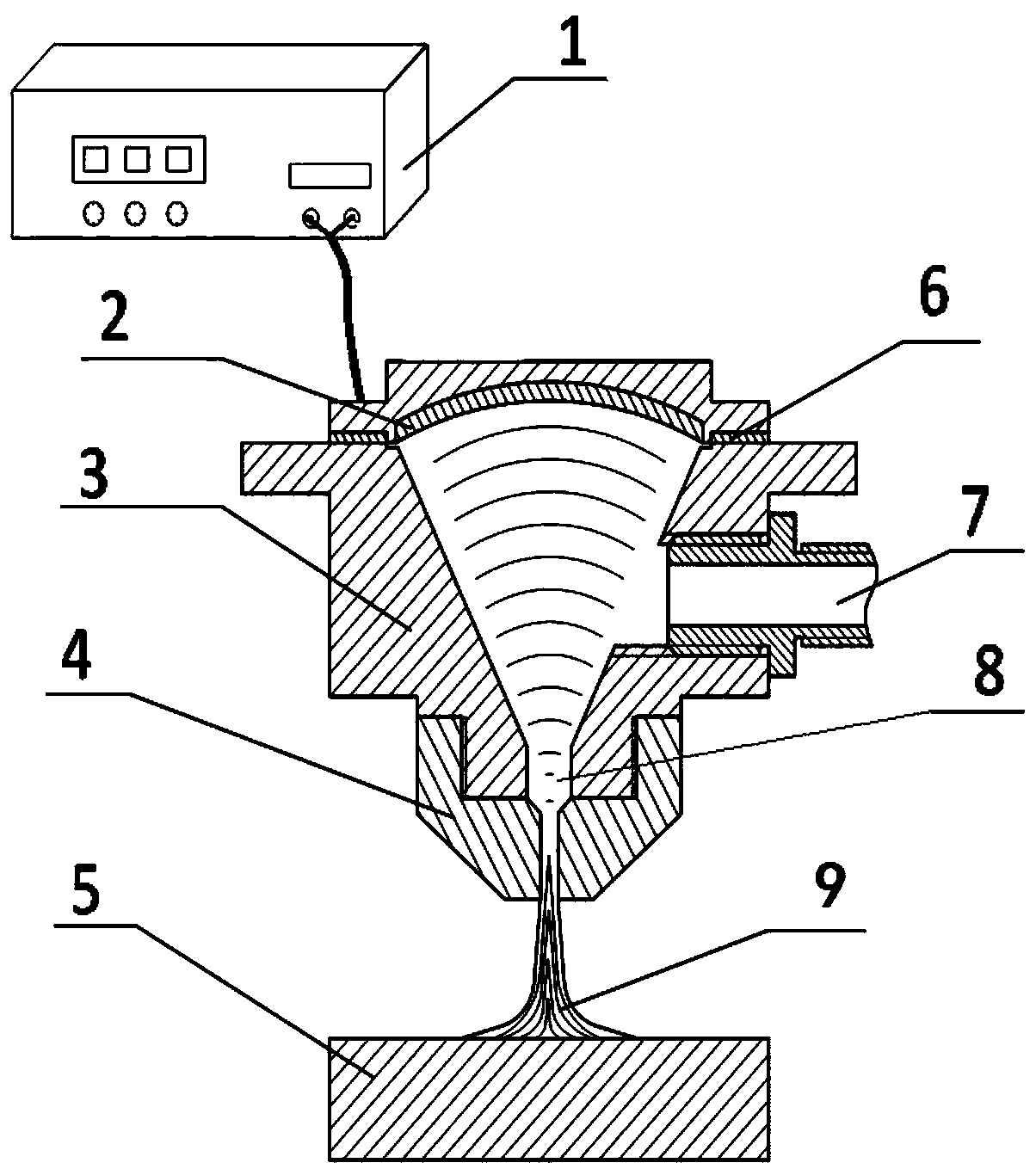
[0033] Preferred Embodiment 1: In this example, the housing 3 of the present invention can be vertically installed on the spindle box above the CNC machine tool table, and the workpiece 5 can be fixed on the machine tool table through the combination of the table and the headstock Move, move the jet nozzle 4 to a suitable position above the surface of the workpiece 5; use a pressure pump to pressurize the polishing liquid 9 pre-mixed with particles to the range of 0.1-10 MPa, and supply the pressurized polishing liquid 9 through the polishing liquid The port 7 is injected into the housing 3, the ultrasonic power supply 1 is turned on, and the polishing liquid 9 after ultrasonic cavitation is sprayed onto the surface of the workpiece 5, and the particles in the polishing liquid 9 are used to wash away the surface of the workpiece 5 processing area to realize the removal of surface material of the workpiece 5. During the machining process, the dwell time and the optimized machinin...

Embodiment 2

[0035] In this example, the housing 3 of the present invention can be installed on an industrial robot manipulator arm that can be flexibly adjusted and moved, and the distance between the jet nozzle 4 and the surface of the workpiece 5 and the surface of the jet nozzle 4 and the workpiece 5 can be controlled by adjusting the manipulator arm. Relative posture. In this way, it can flexibly adapt to the needs of polishing processing of different complex free-form surfaces and the inner surface of the special-shaped cavity.

[0036] The working principle of the present invention: the present invention combines the abrasive water jet polishing device and the principle of focused ultrasound. Ultrasound is an elastic wave with a frequency exceeding 20 kHz. It has short wavelength, high frequency, strong beam performance, and high concentration of energy. Ultrasonic polishing is a polishing method that uses ultrasonic waves as power to push small abrasive particles to impact the surface...


PUM

PropertyMeasurementUnit
Diameteraaaaaaaaaa

Abstract

The invention discloses an ultrasonic cavitation assistant jet polishing system which is characterized by comprising an ultrasonic transducer and a shell; the shell is internally provided with a containing cavity with an opening formed in the upper end; an ultrasonic transducer sealing cover is arranged on an opening formed in the upper end of the containing cavity in a sealing manner; the side surface of the shell is provided with a polishing solution supply hole; the lower side of the shell is provided with a jet nozzle; and the polishing solution supply hole and the jet nozzle communicateswith the containing cavity. The invention further provides an ultrasonic cavitation assistant jet polishing method. The ultrasonic cavitation assistant jet polishing system can be installed on a numerical control machine tool spindle box or an industrial robot mechanical arm, and the ultrasonic transducer is utilized to enable a polishing solution to generate high-frequency vibration and produce cavitation bubbles, and the high-pressure and high-speed polishing solution is sprayed to the surface of a workpiece, so that the material removal efficiency of an abrasive water jet is improved. The ultrasonic cavitation assistant jet polishing system and method provided by the invention can be suitable for surface type finishing of a super-smooth surface and is also suitable for surface processing and manufacturing of a microscopic special morphology.

Description

Technical field [0001] The invention relates to a fluid polishing device and a polishing method, in particular to an ultrasonic cavitation auxiliary jet polishing system and a polishing method. Background technique [0002] At present, with the development of modern optical technology, the demand for high-performance and high-quality optical parts is becoming more and more urgent. At the same time, the requirements for processing equipment and processes for high-quality optical parts are getting higher. At present, a variety of processing methods to obtain high-precision surfaces have been researched. Typical methods include plastic grinding, chemical polishing, float polishing, elastic emission processing, particle beam polishing, jet polishing and so on. However, these typical processing methods may cause damage to the processing surface of the component, or the processing efficiency is too low, or the control is too poor, and each has some defects, so some new processing metho...

Claims


Application Information

Patent Timeline
IPC IPC(8): B24C3/02B24C5/00B24C9/00
CPCB24C3/02B24C5/005B24C9/00
Inventor 曹中臣姜向敏张晓峰林彬张钱
Owner TIANJIN UNIV
Why Eureka
Try Eureka