
A kind of MOS field-controlled thyristor based on Schottky diode and its manufacturing method

A technology of Schottky diodes and manufacturing methods, which is applied in the manufacture of diodes, thyristors, semiconductors/solid-state devices, etc., can solve the problems of current concentration, device fatigue damage, and reduce the efficiency of redundant holes, etc., to solve repeated charging and discharging, Effects of alleviating current concentration and reducing off-time

Active Publication Date: 2020-09-29
XIANGTAN UNIV
View PDF4 Cites 0 Cited by
  • Summary
  • Abstract
  • Description
  • Claims
  • Application Information

AI Technical Summary

Problems solved by technology

However, affected by the oscillating current in the pulse circuit, the off-FET will experience repeated charging and discharging processes
The charging process reduces the efficiency of releasing excess holes and prolongs the time for the MCT to return to the off state
In addition, the current density flowing through the off-FET when the MCT is turned off is two orders of magnitude higher than the current density when the MCT is working normally, and the current distribution of the metal electrode and the semiconductor contact interface of the off-FET is not uniform, especially near the channel. There is an obvious current concentration at the edge of the metal, and the current density at this position will have a very high peak point
MCT is not only affected by the pulse current during the turn-off process, but also has current concentration phenomenon, which makes the power loss have serious inhomogeneity in the spatial distribution, which is easy to cause fatigue damage to the device.

Method used


Image

  • A kind of MOS field-controlled thyristor based on Schottky diode and its manufacturing method
  • A kind of MOS field-controlled thyristor based on Schottky diode and its manufacturing method
  • A kind of MOS field-controlled thyristor based on Schottky diode and its manufacturing method

Examples


Embodiment

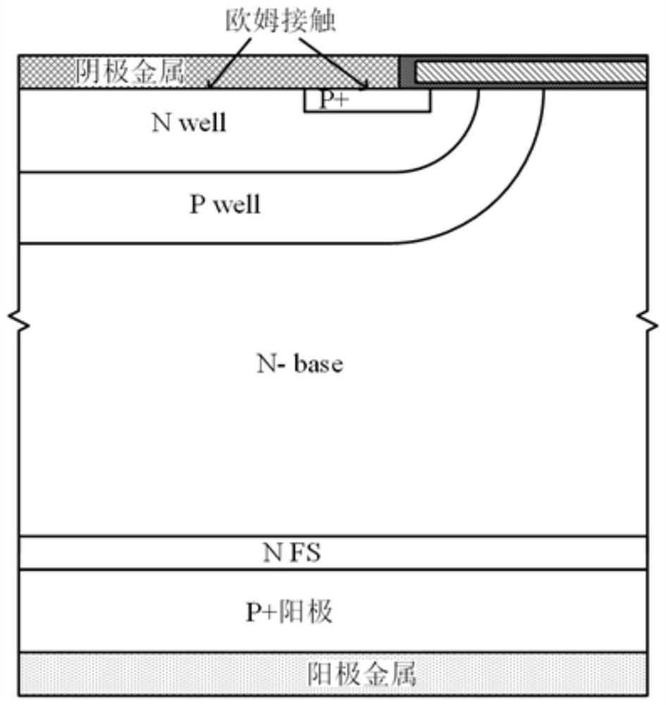
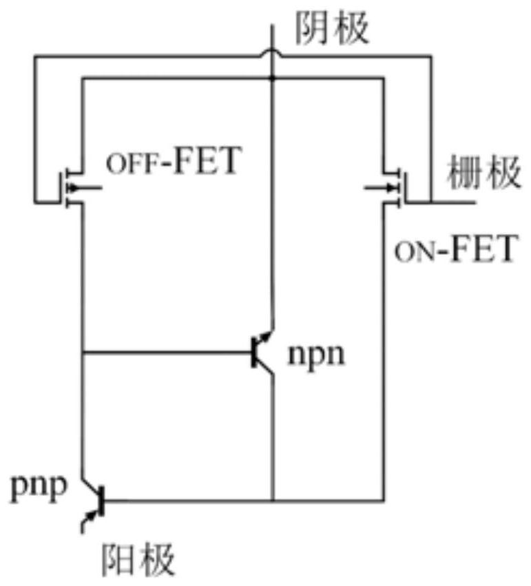
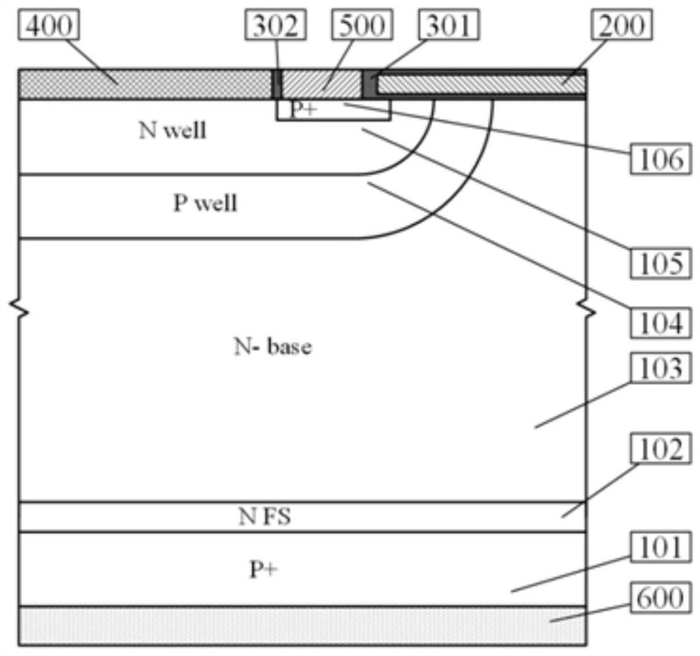
[0055] Taking the traditional MCT structure with a withstand voltage of 1200V and the MCT structure of the present invention as an example for simulation comparison, it is intuitively shown that the present invention has well solved the problem of the conventional MCT turning off the pulse circuit for a long time. MCT structure schematic diagram of the present invention is as image 3 As shown, the equivalent circuit diagram is shown in Figure 4 shown. In order to rule out some potential influencing factors, the simulation uses Figure 5 As shown in the traditional MCT structure, its equivalent circuit is as figure 2 shown. The half-cell width of the two MCTs is 14 μm, and the doping concentration of the P+ region is 4×19 cm -3 , except for the difference in the contact type of the cathode metal, the rest of the structural parameters are the same. In the MCT of the present invention, the work function of the second cathode metal 500 in contact with the P+ region is 4.8 ...


PUM


Abstract

The invention discloses a schottky diode-based MOS field-controlled thyristor. The field-controlled thyristor comprises an anode metal, a P+ anode located on the anode metal, an N FS layer located onthe P+ anode, and an N-base region located on the N FS layer; a first type of cathode metal, a second type of cathode metal and a gate dielectric layer are distributed on the surface of the top layerof the N-base region; a polysilicon gate is arranged above the gate dielectric layer; a P well region is arranged at the top end close to the left side of the N-base region; an N well region is arranged at the top end close to the right side of the P well region; a P+ region is arranged at the top end close to the right side of the N well region; and a part of the N well and the P+ region are located below the polysilicon gate. The method disclosed by the invention can be used for solving the problem of repeated charging and discharging existing in off-FET in an MCT turn-off process, and the turn-off time of the MCT in a pulse circuit is shortened; and meanwhile, the current concentration at the edge of the cathode metal of the MCT is relieved, and the reliability of the device is improved.

Description

technical field [0001] The invention relates to the field of semiconductors, in particular to a Schottky diode-based MOS field-controlled thyristor and a manufacturing method thereof. Background technique [0002] The pulse power switch is an extremely critical link in the pulse power system. Usually, the performance of the switch limits the performance of the pulse power system, such as peak power or repetition rate. Compared with traditional switching devices such as thyristors, semiconductor power devices have the advantages of high efficiency, high repetition frequency, light weight, and low cost. Among them, MOS field-controlled thyristor (MOS Controlled Thyristor, MCT), this kind of semiconductor power device has received extensive attention in pulse power applications. MCT includes the MOS part that plays a controlling role and the thyristor part that works in a high-voltage and high-power environment. After the MCT is turned on, there is a conductance modulation ef...

Claims


Application Information

Patent Timeline
Patent Type & Authority Patents(China)
IPC IPC(8): H01L29/08H01L29/423H01L29/47H01L21/332H01L29/74H01L29/745
CPCH01L29/0834H01L29/42308H01L29/47H01L29/66371H01L29/7412H01L29/7455
Inventor 唐明华孙运龙陈子荷肖永光李刚李诚瞻周维
Owner XIANGTAN UNIV
Learn More