
Flexible electromagnetic wave shielding material, electromagnetic wave shielding type circuit module comprising same and electronic device furnished with same

A shielding material and electromagnetic wave technology, applied in shielding materials, magnetic field/electric field shielding, electrical equipment structural parts, etc., can solve the problems of difficult heat release, low durability, low component function, etc., and achieve excellent heat dissipation performance and flexibility. and excellent wrinkle/recovery properties, preventing deterioration of electromagnetic wave shielding performance

Active Publication Date: 2019-08-02
AMOGREENTECH CO LTD
View PDF12 Cites 5 Cited by
  • Summary
  • Abstract
  • Description
  • Claims
  • Application Information

AI Technical Summary

Problems solved by technology

Therefore, when the element is shielded with an electromagnetic wave shielding material, it is difficult to dissipate the heat generated by the element to the outside, and there is a concern that the function or durability of the element may be reduced.

Method used


Image

  • Flexible electromagnetic wave shielding material, electromagnetic wave shielding type circuit module comprising same and electronic device furnished with same
  • Flexible electromagnetic wave shielding material, electromagnetic wave shielding type circuit module comprising same and electronic device furnished with same
  • Flexible electromagnetic wave shielding material, electromagnetic wave shielding type circuit module comprising same and electronic device furnished with same

Examples


Embodiment 1

[0105] In 85 g of dimethylacetamide and acetone at a weight ratio of 70:30, 12 g of polyvinylidene fluoride was dissolved at a temperature of 80° C. for 6 hours using a magnetic bar to prepare a spinning solution. Put the spinning solution into the solution box of the electrospinning device, and spit it out at a speed of 20 μl / min / hole. At this time, the temperature in the spinning section is kept at 30°C, the humidity is kept at 50%, and the distance between the collector and the tip of the spinning nozzle is 20cm. A high voltage generator is used on the collector to give the spinning nozzle assembly (SpinNozzle Pack) A voltage of 40kV and an air pressure of 0.03MPa were applied to the nozzles of each spinning group to produce a PVDF fiber web with an average diameter of 400nm. Then, in order to dry the solvent and moisture present in the fiber web, at a temperature of 140° C. and 1 kgf / cm 2 Heat and pressure are applied to carry out the calendering process.

[0106] Then, ...

Embodiment 2

[0109] In 88 g of dimethylacetamide and acetone mixed at a weight ratio of 70:30, 12 g of polyvinylidene fluoride was dissolved at a temperature of 80° C. for 6 hours using a magnetic bar to prepare a spinning solution. In the spinning solution, as a conductive filler, spherical silver particles with an average particle diameter of 1.3 μm are mixed so that the volume ratio of polyvinylidene fluoride to silver particles is 1:0.2, accounting for 16.7% of the total volume of the final fiber part, Then, it was dispersed for 12 hours using an ultrasonic disperser. Put the spinning solution into the solution tank of the electrospinning device, stir the solution with an impeller, and spit it out at a speed of 20 μl / min / hole. At this time, the temperature in the spinning section is kept at 30°C, the humidity is kept at 50%, the distance between the collector and the tip of the spinning nozzle is 20cm, and a high voltage generator is used to apply a voltage of 40kV to the spinning nozz...

Embodiment 3~12

[0112] It carried out and produced similarly to Example 2, but as shown in Table 1 or Table 2 below, the content and particle diameter of a conductive filler were changed, and the conductive fiber web shown in Table 1 or Table 2 below was manufactured.


PUM


Abstract

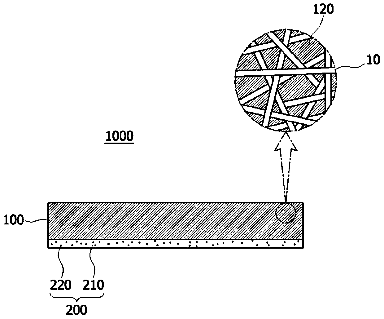
Provided is a flexible electromagnetic wave shielding material. An electromagnetic wave shielding material, according to one embodiment of the present invention, comprises: a conductive fiber web comprising a plurality of pores; and a heat dissipation part provided in at least some of the pores. Due to these features, as the electromagnetic wave shielding material according to the present invention has excellent flexibility, elasticity, and creasing / recovery, it is possible to freely modify the shape thereof as desired and to attach the electromagnetic wave shielding material to be completelyadhered to a surface even if the surface where the material is to be disposed has a curved shape such as uneven or stepped surfaces, and thus it is possible to exhibit excellent electromagnetic wave shielding performance. Also, degradation of the electromagnetic wave shielding performance can be prevented even with various shape changes. Further, since heat dissipation performance is excellent, heat generated in an electromagnetic wave generating source can be rapidly conducted and radiated. In addition, even when parts are mounted with a high density in a narrow area, the electromagnetic waveshielding material can be provided to completely adhere to the mounted parts while overcoming the tight spacing intervals and steps between the parts, such that the flexible electromagnetic wave shielding material can easily be adopted in a compact or flexible electronic device.

Description

technical field [0001] The present invention relates to an electromagnetic wave shielding material, and more specifically, to a flexible electromagnetic wave shielding material capable of exhibiting both heat dissipation performance and electromagnetic wave shielding performance, and an electromagnetic wave shielding circuit including the same, which is excellent in flexibility, stretchability, and wrinkle / restorability Modules and electronic devices incorporating them. Background technique [0002] Electromagnetic waves are a phenomenon in which energy moves in the form of sinusoidal waves while electric and magnetic fields interact with each other, and are usefully used in electronic equipment such as wireless communication or radar. The electric field is generated by voltage and is easily shielded due to long distance or obstacles such as trees. On the contrary, the magnetic field is generated by current and is inversely proportional to distance, but has the characteristi...

Claims


Application Information

Patent Timeline
Patent Type & Authority Applications(China)
IPC IPC(8): H05K9/00H05K7/20
CPCH05K9/009H05K7/20481H05K9/0022D10B2401/16H05K7/2039
Inventor 徐寅踊丁义荣李俊雨
Owner AMOGREENTECH CO LTD
Learn More