Thermal interface composite material, and preparation method and application thereof

A composite material and thermal interface technology, which is applied in the field of thermal interface composite materials and its preparation, can solve the problems of reduced mechanical properties, difficult processing, high cost, etc., achieve excellent thermal conductivity and mechanical properties, reduce the overall interface thermal resistance, and improve the surface area. The effect of external thermal conductivity

Active Publication Date: 2019-08-16
SHENZHEN INST OF ADVANCED TECH CHINESE ACAD OF SCI
View PDF6 Cites 17 Cited by
  • Summary
  • Abstract
  • Description
  • Claims
  • Application Information

AI Technical Summary

Problems solved by technology

[0006] However, in the prior art, thermal interface materials based on compound powder-type thermally conductive fillers have problems such as difficult processing and high cost, and materials with a high proportion of compound powder and good thermal conductivity often have reduced mechanical properties, poor toughness, and are not durable Corrosion; the thermal interface material with carbon nanotubes has excellent performance, but the preparation process of carbon nanotubes is complicated and the cost is high, which is not suitable for industrial application; graphene, as a two-dimensional thermal conductivity material, has anisotropic thermal conductivity, so based on Graphene thermal interface materials exhibit good in-plane thermal conductivity, but low out-of-plane thermal conductivity, making it difficult to achieve good out-of-plane heat dissipation performance

Method used


Image

  • Thermal interface composite material, and preparation method and application thereof
  • Thermal interface composite material, and preparation method and application thereof
  • Thermal interface composite material, and preparation method and application thereof

Examples


Embodiment 1

[0067] This embodiment provides a thermal interface composite material. The specific preparation method includes the following steps:

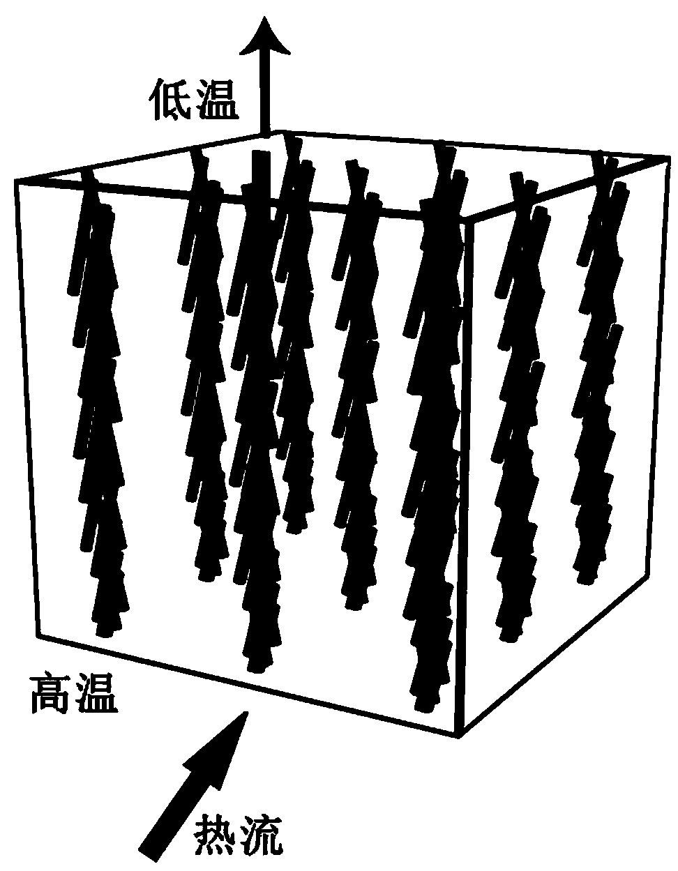
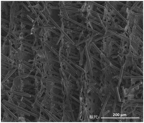
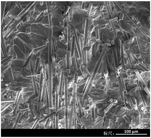
[0068] (1) Preparation of carbon fiber skeleton: Mix 0.8g of carbon fiber powder with surface hydrophilic treatment and an aqueous solution of binder, add appropriate amount of water to make 3mL suspension, stir first with magnet, and then mix under vacuum at 2000rpm After feeding for 20 minutes, a carbon fiber suspension with a volume percentage of carbon fibers of 12% is obtained; then the carbon fiber suspension is frozen with liquid nitrogen and vacuum dried for 24 hours to obtain the carbon fiber skeleton with carbon fibers arranged in a single orientation;

[0069] (2) Preparation of thermal interface composite material: The carbon fiber skeleton obtained in step (1) is completely immersed in epoxy resin, and then placed in a vacuum drying oven, vacuum filtration is carried out at 40°C for 3 hours; followed by gradient heating and curing And ...

Embodiment 2

[0073] This embodiment provides a thermal interface composite material. The specific preparation method includes the following steps:

[0074] (1) Preparation of carbon fiber skeleton: Mix 0.8 g of carbon fiber powder with surface hydrophilic treatment and an aqueous solution of binder, add an appropriate amount of water to make a 3 mL suspension, stir first with magnets, and then mix under vacuum at 1500 rpm. After feeding for 10 minutes, a carbon fiber suspension with a volume percentage of carbon fibers of 12% is obtained; then the carbon fiber suspension is frozen with liquid nitrogen and vacuum dried for 12 hours to obtain the carbon fiber skeleton with carbon fibers arranged in a single orientation;

[0075] (2) Preparation of thermal interface composite material: the carbon fiber skeleton obtained in step (1) is completely immersed in epoxy resin, and then placed in a vacuum drying oven, vacuum filtration is carried out at 30°C for 2 hours; followed by gradient heating and cu...

Embodiment 3

[0077] This embodiment provides a thermal interface composite material. The specific preparation method includes the following steps:

[0078] (1) Preparation of carbon fiber skeleton: Mix 0.8 g of carbon fiber powder with surface hydrophilic treatment and an aqueous binder solution, add a suitable amount of water to prepare 3 mL suspension, stir first with magnets, and then mix in vacuum at 1800 rpm. After 15 minutes, a carbon fiber suspension with a volume percentage of carbon fiber of 12% is obtained; then the carbon fiber suspension is frozen with liquid nitrogen and vacuum dried for 20 hours to obtain the carbon fiber skeleton with carbon fibers arranged in a single orientation;

[0079] (2) Preparation of thermal interface composite material: The carbon fiber skeleton obtained in step (1) is completely immersed in epoxy resin, and then placed in a vacuum drying oven, and vacuum filtration is performed at 35°C for 2.5 hours; then the temperature is gradually increased Curing, ...


PUM

PropertyMeasurementUnit
diameteraaaaaaaaaa
lengthaaaaaaaaaa
pore sizeaaaaaaaaaa

Abstract

The invention provides a thermal interface composite material, and a preparation method and an application thereof. The thermal interface composite material comprises a carbon fiber skeleton, and a polymer matrix for filling and coating the carbon fiber skeleton; and carbon fibers in the carbon fiber skeleton are arranged along a unidirectional manner. The directionally aligned carbon fibers establish a thermal conduction channel in the vertical direction of the thermal interface composite material, and the carbon fibers are mutually contacted and connected in the direction, so the overall interface thermal resistance of the material is reduced, and the out-of-plane thermal conductivity of the thermal interface composite material is greatly improved; and the carbon fiber skeleton and the polymer matrix cooperate with each other, so the thermal interface composite material has a high glass transition temperature and good mechanical properties such as strength and toughness. The thermalinterface composite material provided by the invention has excellent thermal conduction property and excellent mechanical properties, and the preparation method is simple, and is easy to operate, so the material is a novel thermal conduction material with a large-scale industrial production prospect.

Description

Technical field [0001] The invention belongs to the technical field of polymer composite materials, and specifically relates to a thermal interface composite material and a preparation method and application thereof. Background technique [0002] The miniaturization and high integration of electronic components not only endow electronic products with more functions and higher efficiency, but also greatly increase the working power per unit volume in electronic products, which brings about serious heat dissipation problems. The dissipation and heat generation of electronic components will directly lead to an increase in the temperature and thermal stress of electronic equipment, which poses a serious threat to the working reliability of microelectronic equipment. The most important heat dissipation design of electronic components is to rely on thermal interface materials to connect the chip to the substrate and the heat dissipation system of the substrate. The industry generally b...

Claims


Application Information

Patent Timeline
Patent Type & Authority Applications(China)
IPC IPC(8): C08L63/00C08K9/00C08K7/06C08J5/24
CPCC08J5/24C08J2363/00C08K9/00C08K7/06
Inventor 孙蓉马加珂曾小亮么依民许建斌
Owner SHENZHEN INST OF ADVANCED TECH CHINESE ACAD OF SCI
Why Eureka
Try Eureka