
Oxidation device and process for NOx in flue gas

A nitrogen oxide and oxidation device technology, applied in the field of flue gas pollutant removal, can solve the problems of consumption, inability to be popularized and applied on a large scale, high operating cost of ozone oxidation, etc., and achieve the effect of high oxidation rate

Pending Publication Date: 2019-08-30
CHINA HUANENG GRP CO LTD +1
View PDF0 Cites 1 Cited by
  • Summary
  • Abstract
  • Description
  • Claims
  • Application Information

AI Technical Summary

Problems solved by technology

In addition, about 10kg of liquid oxygen is needed to produce 1kg of ozone, so a 600MW unit needs to consume 16t / h of liquid oxygen
The consumption of electricity and liquid oxygen makes the operation cost of ozone oxidation higher, and it is not yet possible to promote and apply it on a large scale.

Method used


Image

  • Oxidation device and process for NOx in flue gas
  • Oxidation device and process for NOx in flue gas
  • Oxidation device and process for NOx in flue gas

Examples


Embodiment 1

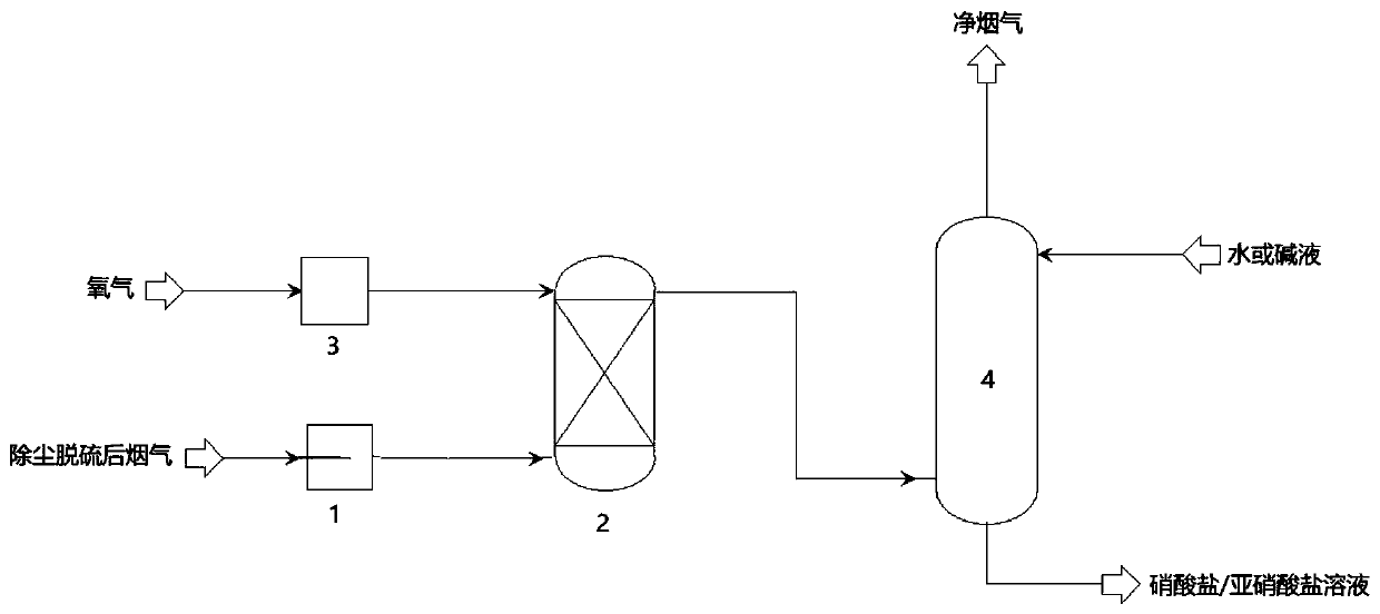
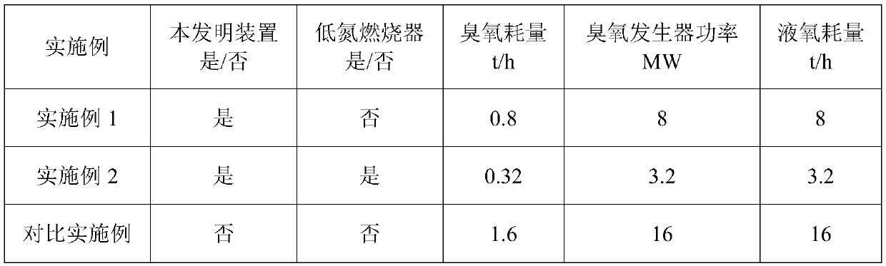
[0037] Example 1: Taking a 600MW unit as an example, the flue gas volume is 2 million standard cubic meters, and the NO content in the flue gas is 500mg / Nm 3 After the flue gas is dedusted and desulfurized, it enters the oxidation tower 2, and the oxidation tower 2 is filled with ZSM-5 hydrophobic molecular sieve. Block; ZSM-5 hydrophobic molecular sieve has an adsorption and oxidation rate of NO of 50% under the condition of wet flue gas after desulfurization, and the concentration of residual NO in the flue gas after adsorption and oxidation of the adsorption bed is 250mg / Nm 3 , the ozone production rate of the ozone generator 3 is 0.8t / h, the power is 8MW, the liquid oxygen consumption is 8t / h, the final oxidation rate of NO is 99%, and the NO content in the flue gas at the outlet of the oxidation tower 2 is 5mg / Nm 3 , absorbing NO through the wet absorption tower 4 2 After that, the NO in the net flue gas x The content is 5mg / Nm 3 .

Embodiment 2

[0038] Example 2: Taking a 600MW unit equipped with a low-nitrogen burner as an example, the flue gas volume is 2 million standard cubic meters, and the NO content in the flue gas is 200mg / Nm 3 .

[0039] The technical process is the same as in Example 1, and the NO content in the flue gas after adsorption and oxidation of the oxidation tower 2 adsorption bed is 100mg / Nm 3 The ozone production rate of the ozone generator 3 is 0.32t / h, the power is 3.2MW, the liquid oxygen consumption is 3.2t / h, the NO final oxidation rate is 99%, and the NO in the net flue gas discharged from the wet absorption tower 4 x The content is 5mg / Nm 3 .


PUM


Abstract

The invention discloses an oxidation device for NOx in flue gas. The oxidation device comprises an oxidation tower and an ozone generator, wherein an oxidation medium inlet is formed in the oxidationtower, a fixed bed of the oxidation tower is provided with a physical adsorption layer, and the oxidation medium inlet is higher than the top end of the physical adsorption layer; an oxidation mediumoutlet of the ozone generator is communicated with the oxidation medium inlet of the oxidation tower, a flue gas inlet of the oxidation tower is communicated with a flue gas output pipeline, and a flue gas outlet of the oxidation tower is communicated with a chimney through a flue. The invention also discloses an oxidation process, in combination with advantages and disadvantages of physical adsorption enrichment oxidation and ozonation, physical adsorption enrichment oxidation is adopted in an area with higher Nox in flue gas at the inlet of the oxidation tower, and part of NO is oxidized into NO2 under the condition that an additional oxidizing agent and energy are not consumed; when the NO concentration is reduced to a certain degree, ozone is further adopted for deep oxidation, so thatNO which is difficult to remove by wet absorption in NOx is oxidized to NO2 easy to absorb. The oxidation device can realize high oxidation rate of NO under the condition that little ozone is consumed.

Description

technical field [0001] The invention belongs to the technical field of flue gas pollutant removal, and in particular relates to a flue gas nitrogen oxide oxidation device and process. Background technique [0002] The flue gas produced by coal combustion contains a large amount of nitrogen oxides NOx, which is one of the main causes of air pollution. At present, NOx in the flue gas is mainly removed by the SCR selective catalytic reduction method. In this method, NOx is added to the NH in the flue gas under the action of the catalyst. 3 Revert to harmless N 2 , and then removed. Although the SCR denitrification technology is quite mature, there are still many problems. For example, the catalyst only has high activity in a specific temperature range. When the power plant operating load is adjusted, the change of flue gas temperature will seriously affect the SCR denitrification efficiency. In addition, SCR denitrification has secondary pollution problems such as ammonia e...

Claims


Application Information

Patent Timeline
IPC IPC(8): B01D53/56B01D53/78B01D53/76
CPCB01D53/04B01D53/56B01D53/76B01D53/78B01D2251/104
Inventor 汪世清郭东方牛红伟刘练波郜时旺
Owner CHINA HUANENG GRP CO LTD
Learn More