Recording electrode with S-shaped metal shielding structure and preparation technology

A technology of recording electrodes and metal shielding, which is applied in the field of neural microelectrodes, can solve problems such as inability to deform, inability to synchronize light stimulation, and failure to consider the influence of electromagnetic interference on the micro-LED chip array layer, so as to improve the acquisition quality and signal-to-noise ratio, Effect of reducing the influence of electromagnetic interference

Active Publication Date: 2019-09-27
SHANGHAI JIAO TONG UNIV
View PDF4 Cites 7 Cited by
  • Summary
  • Abstract
  • Description
  • Claims
  • Application Information

AI Technical Summary

Problems solved by technology

However, the application of this type of structure is limited to Michigan silicon needle electrodes, and cannot be applied to flexible electrodes for optoelectronic integration.
[0005] KimT, McCallJG and others from the University of Illinois at Urbana-Champaign in the United States wrote "Injectable, cellular-scale optoelectronics with applications for wireless optogenetics" in Science, 2013, 340 (6129): 211-216, proposing to integrate micro LED chips, recording electrodes, light and temperature sensors on flexible substrates On the above, a multi-functional flexible needle-like piercing electrode was obtained, which was used in the study of the mouse deep brain optogenetics model, but did not consider the influence of electromagnetic interference introduced by the micro-LED chip array layer; in the same year, KwonKY, Michigan State University, SirowatkaB et al wrote "Opto-μECoGarray: Ahybrid neural interface with transparent μECoGelectrode array and integrate dLEDs for optogenetics" in IEEE transactions on biomedical circuits and systems, 2013, 7 (5): 593-600, proposing to integrate micro-LED chip arrays and ITO recording electrodes on flexible substrates to obtain flexible photoelectric electrodes for The study of the optogenetic model of the rat cerebral cortex also did not consider the influence o

Method used


Image

  • Recording electrode with S-shaped metal shielding structure and preparation technology
  • Recording electrode with S-shaped metal shielding structure and preparation technology
  • Recording electrode with S-shaped metal shielding structure and preparation technology

Examples


Example Embodiment

[0045] The present invention will be described in detail below in conjunction with specific embodiments. The following examples will help those skilled in the art to further understand the present invention, but do not limit the present invention in any form. It should be pointed out that for those of ordinary skill in the art, a number of modifications and improvements can be made without departing from the concept of the present invention. These all belong to the protection scope of the present invention.
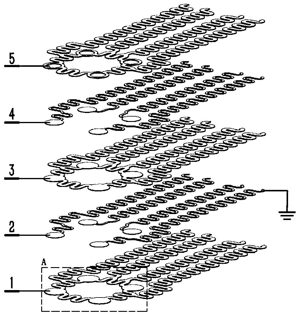
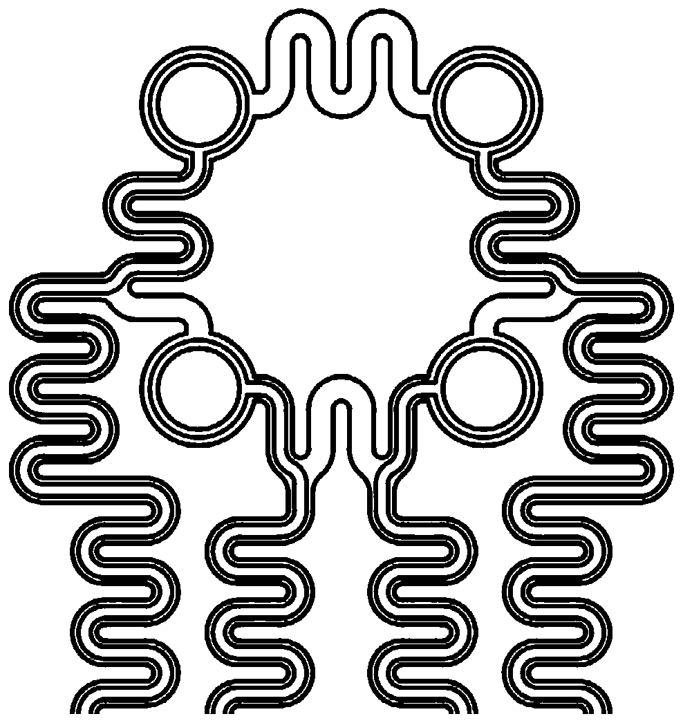
[0046] Referring to FIG. 1, in an embodiment of the recording electrode with a serpentine metal shield structure of the present invention, the recording electrode is provided with a serpentine metal shielding layer 2, and the serpentine metal shielding layer 2 is located between the electromagnetic interference source and the metal electrode layer. Between, used to reduce electromagnetic interference.

[0047] When active devices such as miniature light-emitting diode chips ...


PUM

PropertyMeasurementUnit
Thicknessaaaaaaaaaa
Thicknessaaaaaaaaaa
Thicknessaaaaaaaaaa

Abstract

The invention provides a recording electrode with an S-shaped metal shielding structure and a preparation technology. The recording electrode is provided with an S-shaped metal shielding layer, and the S-shaped metal shielding layer is located between an electromagnetic interference source and a metal electrode layer and used for attenuating electromagnetic interference. The recording electrode further comprises an S-shaped polymer substrate layer, an S-shaped polymer intermediate insulating layer, an S-shaped metal electrode layer and an S-shaped polymer packaging layer, each structural layer adopts an S-shaped bending structure, and the integrated flexible photoelectric electrode has stretchability, can collect neutral signals normally in a certain deformation range and meets the actual application demands. The invention further provides a preparation technology of the recording electrode with the S-shaped metal shielding structure. The prepared recording electrode not only can effectively reduce influence of the electromagnetic interference on neural signal collection quality, but also can deform with electrode structure stretching and can be applied to animal tissue with deformation.

Description

technical field [0001] The invention relates to a neural microelectrode in the technical field of biomedical engineering, in particular to a recording electrode with a serpentine metal shielding structure and a preparation process. Background technique [0002] As a bridge between neural tissue and external devices, neural interfaces are not only widely used in neuroscience research, but also provide effective treatments for neurological diseases such as Parkinson's disease, depression, and stroke. With the advent of optogenetics, by introducing a light source with a specific wavelength and a small size into the neural interface, it is possible to activate or inhibit a specific type of neuron in the sub-millimeter region to achieve high-resolution optical neuromodulation. , has increasingly become one of the indispensable tools in neuroscience and brain science research. [0003] However, in the process of integrating micro-LED chips or micro-LD chips with a size of tens to...

Claims


Application Information

Patent Timeline
IPC IPC(8): A61B5/0478A61B5/0484A61B5/00
CPCA61B5/6868A61B2503/40A61B2503/42A61B2562/0209A61B2562/125A61B2562/182A61B5/291A61B5/377
Inventor 刘景全吉博文郭哲俊王隆春
Owner SHANGHAI JIAO TONG UNIV
Why Eureka
Try Eureka