Three-degree-of-freedom crank connecting rod mechanical all-electric servo numerical control plate material bending machine
A crank-connecting-rod, mechanical technology, applied in the field of sheet metal bending machines, can solve the problems of low power utilization rate, incomplete application of motor power, and high power of the drive motor, so as to improve performance, achieve high-speed heavy-duty, safety high sex effect
- Summary
- Abstract
- Description
- Claims
- Application Information
AI Technical Summary
Problems solved by technology
Method used
Image

Examples
Embodiment 1
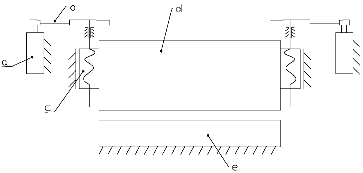
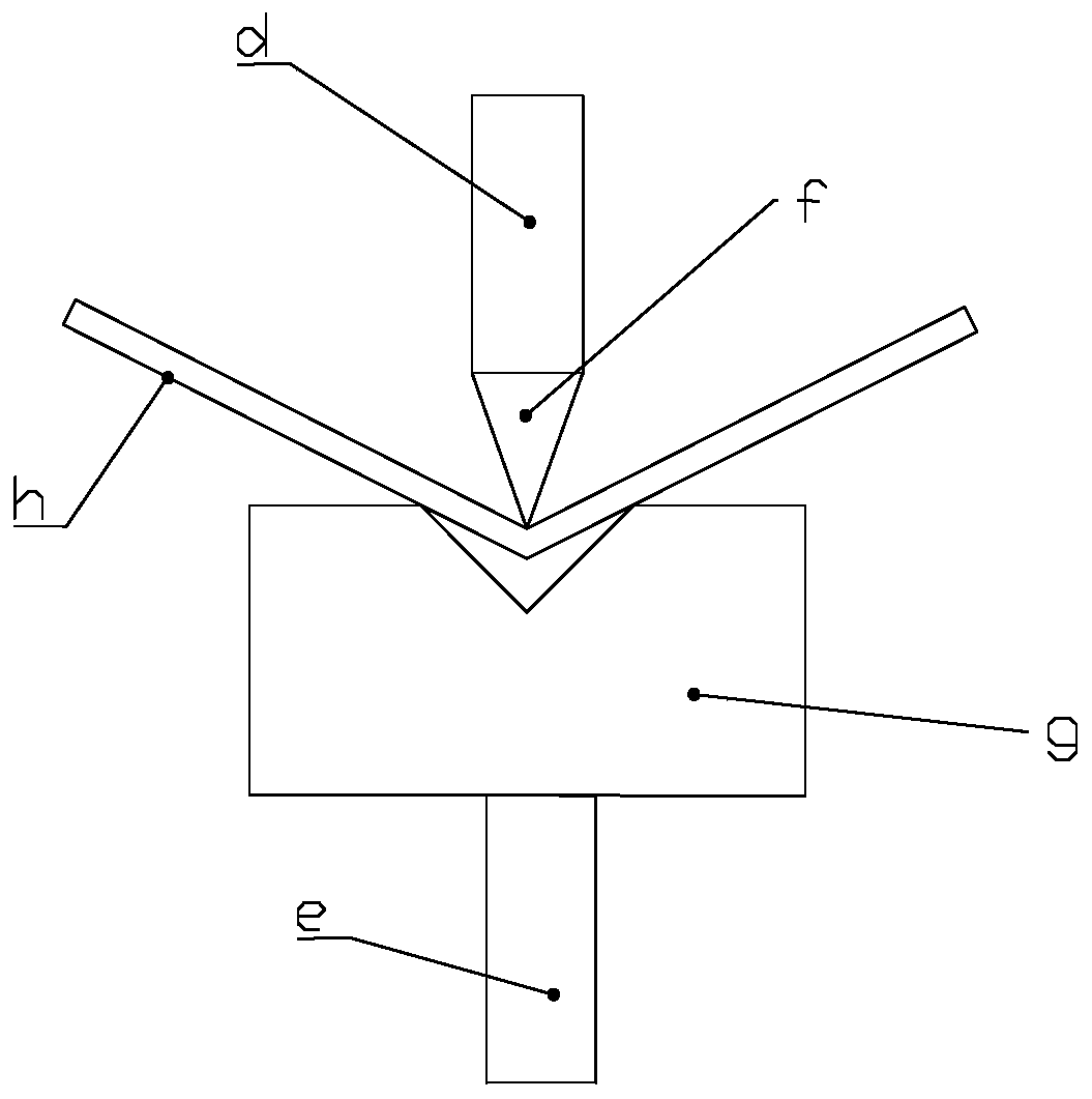
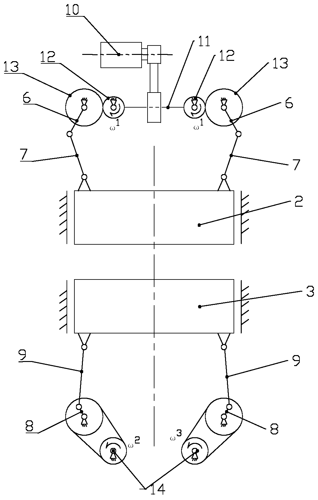
[0045] Such as image 3 , Figure 4 with Figure 5 As shown, a three-degree-of-freedom crank-link mechanical all-electric servo numerical control sheet metal bending machine of the present invention includes a frame 1 , an upper slider 2 , a lower slider 3 , an upper mold 4 and a lower mold 5 . The upper slider 2 and the lower slider 3 are arranged opposite up and down, and can move up and down along the frame. The upper slider 2 is symmetrically provided with upper guide grooves 24 for guiding sliding, and the corresponding position on the frame is provided with an insertion upper guide. Groove 24 can slide up and down along the upper guide block 25 of upper guide groove 24; The lower guide groove 26 that is used for guiding sliding is symmetrically arranged on the lower slider 3, and the corresponding position on the frame is provided with inserting the lower guide groove 26 to be able to slide along the bottom. The lower guide block 27 that guide groove 26 slides up and d...
Embodiment 2
[0056] The structure of embodiment 2 is the same as that of embodiment 1, the difference is that the length of the upper crank 6 is shorter than the length of the lower crank 8, the upper drive mechanism drives the upper slider to realize low-speed and small-stroke movement, and the lower drive mechanism drives the lower slider Realize high-speed and large-stroke movement. The working condition of the bending machine is a typical variable speed and variable load condition. The fast down and return stages are high-speed, low-load and large-stroke motion stages, and the working stage is low-speed, large-load and small-stroke motion stages. Therefore the present invention adopts lower drive mechanism to drive lower slider to realize fast down and return stage, and upper drive mechanism drives upper slider to realize work progress stage.
PUM
 Abstract
Description
Claims
Application Information
PatSnap Eureka turns technology decisions into work you can execute. Powered by our Innovation Knowledge Graph, it runs expert workflows across engineering, life sciences, materials and intellectual property. Get your review-ready output in minutes.


