
A laser drilling device and method for improving hole quality based on underwater drilling

An underwater laser and laser drilling technology, which is applied to laser welding equipment, manufacturing tools, metal processing equipment, etc., can solve the problems of poor versatility of directional chemical etching, high cost of femtosecond lasers, and high processing conditions, and achieve improvement. The roundness of the forming hole is poor, the phenomenon of micro-cracks is improved, and the effect of reducing the recasting layer

Active Publication Date: 2021-06-22
JIANGSU UNIV
View PDF8 Cites 0 Cited by
  • Summary
  • Abstract
  • Description
  • Claims
  • Application Information

AI Technical Summary

Problems solved by technology

Abrasive flow grinding is based on the principle of least resistance. Large holes have more material removed, and small holes have little or no material removal. The hole expansion is uneven and there is a recast layer that cannot be removed from the processing "dead angle" area. especially in the middle of the hole
The overall chemical corrosion method also has a corrosive effect on the workpiece substrate, while the directional chemical corrosion method has poor versatility, and different metal materials or organizational structures require different directional corrosion solutions
After millisecond laser drilling parameters are optimized, the thickness of the recast layer can be significantly reduced, but there is still a thin recast layer; femtosecond secondary processing can completely remove the recast layer, but the femtosecond laser is expensive, requires high processing conditions, and has high efficiency. Low

Method used


Image

  • A laser drilling device and method for improving hole quality based on underwater drilling
  • A laser drilling device and method for improving hole quality based on underwater drilling
  • A laser drilling device and method for improving hole quality based on underwater drilling

Examples


Embodiment Construction

[0034] In order to better illustrate the implementation details of the present invention, the technical solutions of the present invention will be further described below in conjunction with the accompanying drawings.

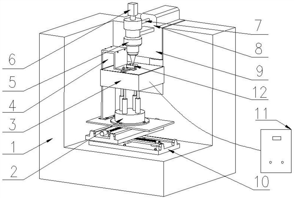
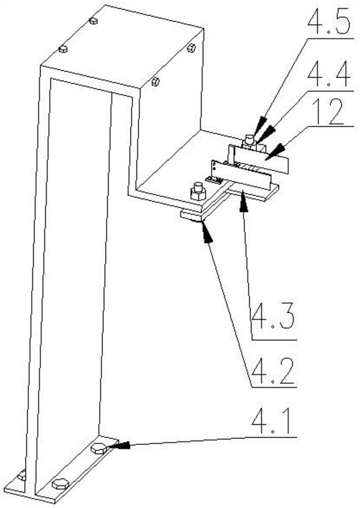
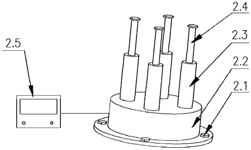
[0035] combined with figure 1 , a laser drilling device for improving hole taper and inner wall quality, characterized in that it includes a power supply box 1, an electric push rod 2, a cuboid container without a cover 3, a workpiece fixture 4, a laser head 5, a CCD camera 6, and a light guide tube 7. Laser 8, z-direction moving mechanism 9, x-y moving platform 10;

[0036] Described power box 1 is installed on the left side vertical surface of machine tool base, and x-y mobile platform 10 is installed on the base upper surface of machine tool, and electric push rod 2 and workpiece fixture 4 are installed on described x-y mobile platform 10, and described electric A cuboid container 3 without a cover is installed on the push rod 2, a z-direction moving mechan...


PUM


Abstract

The invention discloses a laser drilling device and method for improving the quality of drilling based on underwater laser drilling, and relates to the field of laser drilling. The laser beam emitted by the laser head and the three-dimensional position of the workpiece can be changed. The laser head includes a first A plane reflector, a half-wave plate, a second plane reflector, a spatial light modulator, a 1 / 4 wave plate, a third plane reflector and a focusing lens; the laser beam emitted by the laser head irradiates the first plane On the mirror, it is reflected by the first plane mirror to the half-wave plate, and then reflected to the spatial light modulator by the second plane mirror; after passing through the 1 / 4 wave plate, it is irradiated to the third plane mirror again, and after focusing The lens is focused to irradiate the workpiece. The problems of recasting layer and burrs in the prior art are solved by changing the structure of the laser and adding interdigitated electrodes above the workpiece.

Description

technical field [0001] The invention relates to the technical field of laser drilling, in particular to a laser drilling device for improving the quality of drilling based on underwater drilling. Background technique [0002] In order to meet the performance requirements of advanced engines such as high thrust-to-weight ratio and high combustion efficiency, the hot-end parts of the engine (such as combustion chambers, turbine blades, etc.) work at extremely high temperatures. At present, the inlet temperature of the advanced engine has reached above 1650°C, which is much higher than the maximum withstand temperature of the most advanced fifth-generation single crystal nickel-based superalloy of 1300°C, so the hot end parts of the engine are widely used in film cooling technology . The diameter of the film cooling hole is generally between 0.20 and 1.25mm, and the ratio of depth to diameter is large, and there are hundreds of film holes distributed on a single blade, and eve...

Claims


Application Information

Patent Timeline
Patent Type & Authority Patents(China)
IPC IPC(8): B23K26/382
CPCB23K26/382
Inventor 任乃飞宋诗文王后孝夏凯波石春辉李涛高福强范永胜
Owner JIANGSU UNIV
Learn More