System and method for capturing and utilizing CO2 in low energy consumption by coupling new energy

A low-energy, new energy technology, applied in the field of energy technology and environmental protection, can solve the problems of increasing capital investment and operating costs, and achieve the effect of reducing energy consumption

Inactive Publication Date: 2019-10-08
SOUTHEAST UNIV
View PDF8 Cites 3 Cited by
  • Summary
  • Abstract
  • Description
  • Claims
  • Application Information

AI Technical Summary

Problems solved by technology

To achieve oxyfuel combustion, an air separator must be added, which greatly increases capital investment and operating costs

Method used


Image

  • System and method for capturing and utilizing CO2 in low energy consumption by coupling new energy
  • System and method for capturing and utilizing CO2 in low energy consumption by coupling new energy

Examples


Embodiment 1

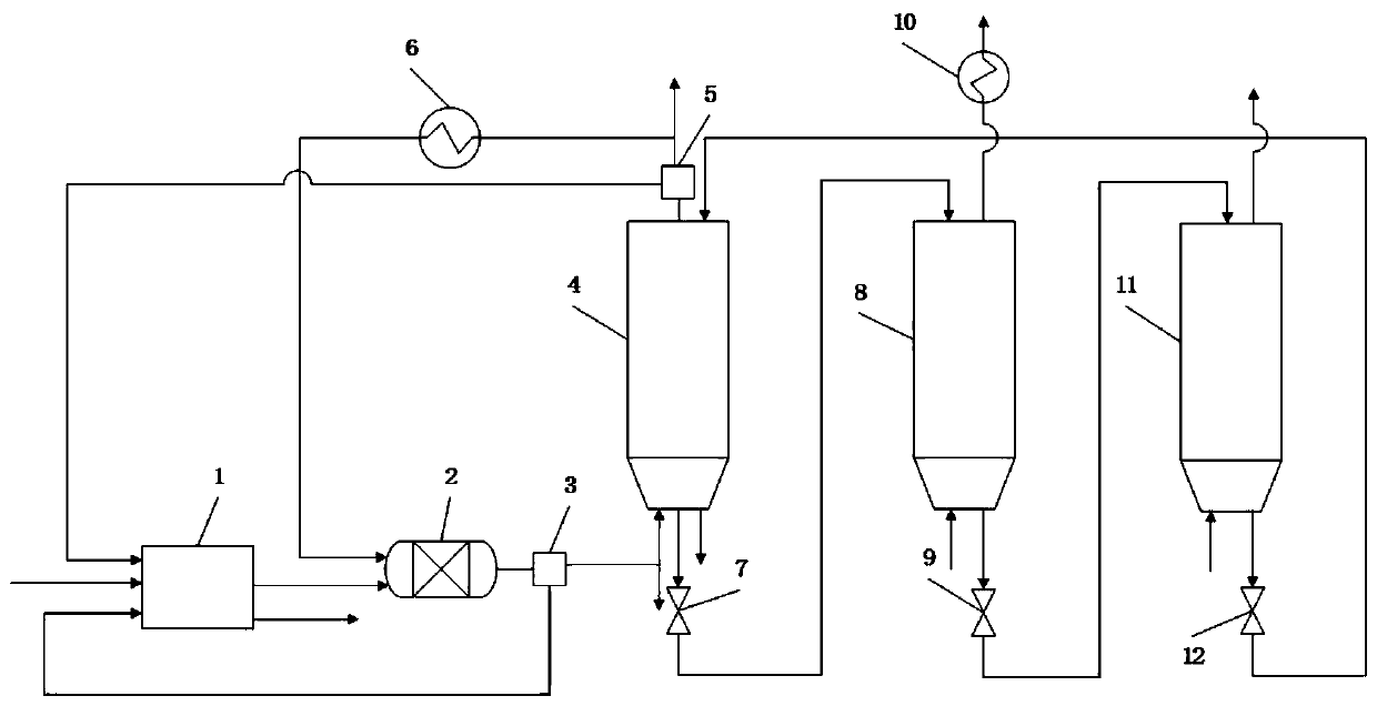
[0038] like figure 1 As shown, a coupling new energy low energy consumption to achieve CO 2 Capture and utilization system, including electrolysis water reactor 1, methanation reactor 2, calcination / reduction reactor 4, air reactor 8, carbonation reactor 11; calcination / reduction reactor 4, air reactor 8 and carbonic acid The chemical reactor 11 is connected circularly, the electrolytic water reactor 1 is connected with the methanation reactor 2 in turn, and then the methanation reactor 2 is connected with the calcination / reduction reactor 4 after going through the condenser A3.

[0039] Calcination\reduction reactor 4 is connected to heat exchanger A6 through condenser B5, heat exchanger A6 is connected to methanation reactor 2, and condenser B5 is also connected to electrolysis water reactor 1; air reactor 8 is connected at one end There is heat exchanger B10.

[0040] Calcination / reduction reactor 4 and air reactor 8, air reactor 8 and carbonation reactor 11, carbonation ...

Embodiment 2

[0042] A coupling of new energy and low energy consumption to achieve CO 2 The method of capturing and utilizing includes the following steps:

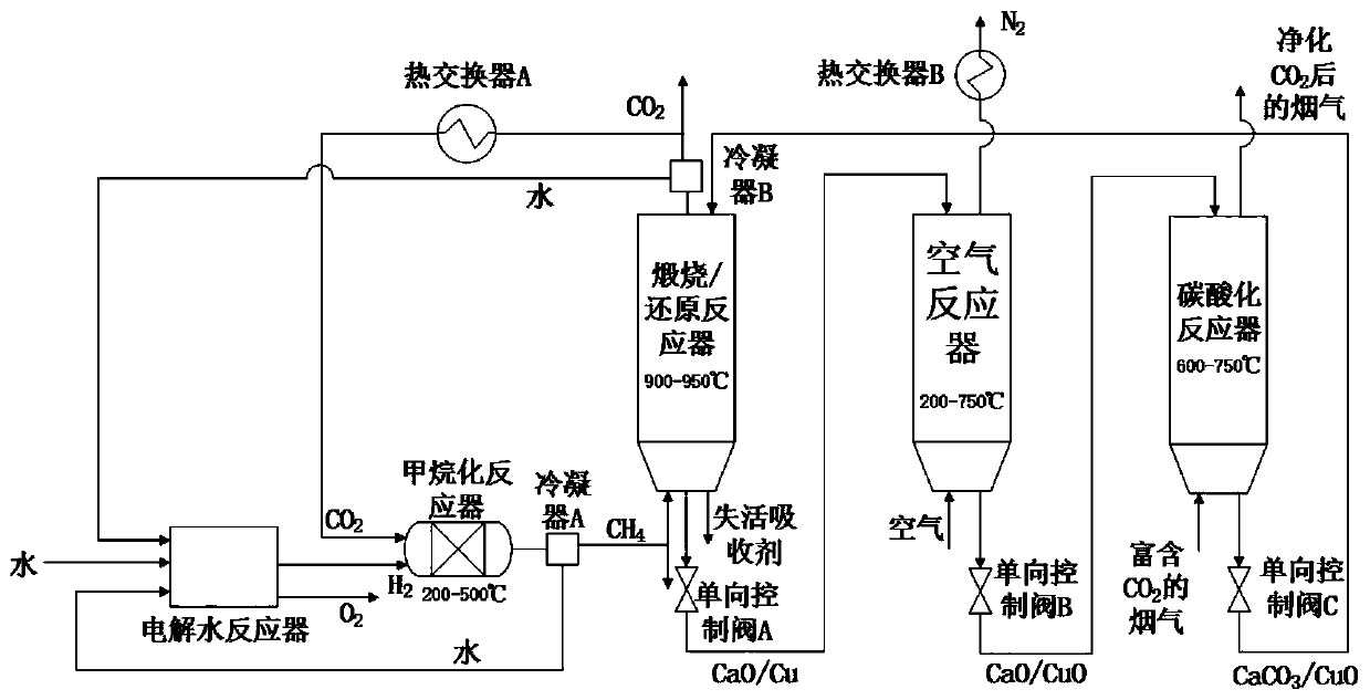
[0043] (1) The oxidized oxygen carrier and calcium-based absorbent enter the calcination / reduction reactor 4 together, and the oxidized oxygen carrier and CH 4 Reduction takes place in calcination / reduction reactor 4 to generate CO 2 and H 2 O, and release heat to calcine the calcium-based absorbent to generate CaO and CO 2 . The oxygen carrier is nickel-based oxygen carrier, and the calcium-based absorbent is CaO / Ca(OH) 2 / CaCO 3 , the calcining temperature of the calcium-based absorbent is 950°C, and the reaction pressure is normal pressure.

[0044] (2) Generated CO 2 and H 2 O separates CO through condenser B5 2 and H 2 O, where H 2 O is sent to electrolysis water reactor 1 as raw material, while CO 2 After the heat is recovered by the heat exchanger A6, the H 2 Mixed in Methanation Reactor 2, CO 2 Methanation reacti...

Embodiment 3

[0049] like figure 1 and 2 As shown, a coupling new energy low energy consumption to achieve CO 2 The method of capturing and utilizing includes the following steps:

[0050] (1) The oxidized oxygen carrier and calcium-based absorbent enter the calcination / reduction reactor 4 together, and the oxidized oxygen carrier and CH 4 Reduction takes place in calcination / reduction reactor 4 to generate CO 2 and H 2 O, and release heat to calcine the calcium-based absorbent to generate CaO and CO 2 . The oxygen carrier is copper-based oxygen carrier, and the calcium-based absorbent is CaCO 3 , the temperature for calcining the calcium-based absorbent is 940°C, and the reaction pressure is normal pressure.

[0051] (2) Generated CO 2 and H 2 O separates CO through condenser B5 2 and H 2 O, where H 2 O is sent to electrolysis water reactor 1 as raw material, while CO 2 After the heat is recovered by the heat exchanger A6, the H 2 Mixed in Methanation Reactor 2, CO 2 Methana...


PUM


Abstract

The invention discloses a system and a method for capturing and utilizing CO2 in low energy consumption by coupling new energy. The system comprises an electrolytic water reactor, a methanation reactor, a calcining / reducing reactor, an air reactor and a carbonation reactor, the calcining / reducing reactor, the air reactor and the carbonation reactor are circularly connected and used for capturing CO2 in flue gas in a low energy consumption manner, the electrolytic water reactor and the methanation reactor are sequentially connected, and the methanation reactor is connected with the calcining / reducing reactor and used for synthesizing methane. According to the system and the method, the CO2 is captured, utilized and coupled, the new energy electrolyzes water to prepare hydrogen, methanationof the CO2 by hydrogenation is achieved, zero-carbon emission of the system is achieved, and poly-generation of gases such as high-concentration CO2, CH4, O2, N2 and H2 is achieved.

Description

technical field [0001] The invention belongs to the intersecting field of energy technology and environmental protection technology, and specifically relates to a method of coupling new energy with low energy consumption to realize CO 2 The capture and utilization system and its coupling with new energy and low energy consumption realize CO 2 methods of capture and utilization. Background technique [0002] According to the latest report of the International Energy Agency, the global energy-related CO in 2017 2 Emissions reached 32.53 billion tons, an increase of 1.4% year-on-year. And with CO 2 The massive emission of greenhouse gases as the main component will cause a series of greenhouse effects such as global warming and sea level rise. Therefore, the development of efficient and low-cost CO 2 Capture technology is a research hotspot in the world today. [0003] Calcium-based absorbent has the advantages of low price and abundant reserves, and its calcination / carbo...

Claims


Application Information

Patent Timeline
Patent Type & Authority Applications(China)
IPC IPC(8): C10L3/08C10L3/10C25B1/04
CPCC10L3/08C10L3/104C25B1/04Y02E60/36Y02P20/10
Inventor 段伦博陈健薛现恒孙朝李林石田卞若愚周琳绯
Owner SOUTHEAST UNIV
Why Eureka
Try Eureka