
A carbon dioxide mineralization power generation method using organic matter as a catalyst

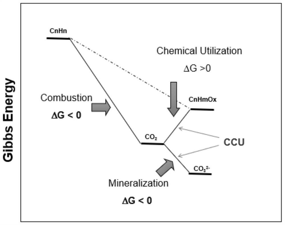
A carbon dioxide and organic matter technology, applied in the field of carbon dioxide mineralization and power generation, can solve the problems of low power generation efficiency and high cost, and achieve the effect of reducing production costs and reducing CO2 emissions

Inactive Publication Date: 2020-12-01
SICHUAN UNIV
View PDF6 Cites 0 Cited by
  • Summary
  • Abstract
  • Description
  • Claims
  • Application Information

AI Technical Summary

Problems solved by technology

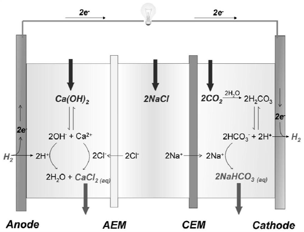
Taking advantage of the redox characteristics of organic substances like riboflavin, it can be introduced into CO 2 Mineralized power generation technology to replace the original CO 2 H in Mineralized Power Generation Technology 2 , using industrial alkaline waste (mainly Ca(OH) 2 ), carbon dioxide as raw materials, efficient power generation and output of high-purity CaCO 3 , solves the current CO 2 Due to the high cost and low power generation efficiency brought about by noble metal catalysts in mineralized power generation, CO 2 Emission reduction offers new direction

Method used


Image

  • A carbon dioxide mineralization power generation method using organic matter as a catalyst
  • A carbon dioxide mineralization power generation method using organic matter as a catalyst
  • A carbon dioxide mineralization power generation method using organic matter as a catalyst

Examples


Embodiment 1

[0041] The technical process of this embodiment is as attached Figure 4 and 5 shown. The effective area in the electrolytic cell is 4cm 2 electrolyzer. The electrolytic cell is divided into two areas, the anode area and the cathode area, by a cation exchange membrane that only allows cations to pass through but prevents anions from passing through.

[0042] Add 50ml of NaOH, 0.4mol / LNH2, 1mol / L KCl solution with a concentration of 1.4mol / L in the anode area as the anolyte, and add 50ml of NaHCO with a concentration of 1.mol / L 3 , 0.4mol / L N and 1mol / L KCl solution to the cathode area as the electrolyte and at the same time as the reaction raw material, connected to the load.

[0043] The program of load output electricity is to increase the current by 0.001A per second until the voltage will be 0 and stop. Initially, the load output function is not turned on, and the open circuit voltage displayed by the load will increase from 0V until the open circuit voltage increases...

Embodiment 2

[0045] The technical process of this embodiment is as attached figure 1 and 2 shown. The electrolytic cell is divided into two areas, the anode area and the cathode area, by a cation exchange membrane that only allows cations to pass through but prevents anions from passing through. Add 100ml of NaOH, 0.4mol / LNH2, 1mol / L KCl solution with a concentration of 1.4mol / L in the anode area as the anolyte, and add 100ml of NaHCO with a concentration of 1.mol / L 3 , 0.4mol / L N and 1mol / L KCl solution to the cathode area as the electrolyte and at the same time as the reaction raw material, connected to the load. At the same time, two other identical anode and cathode electrolysis preparations were prepared for use.

[0046] Load fixed current 100ml, output power density is 83.6W / m 2 , After about 10 hours of stable power generation, replace the electrolyte with a spare solution to continue power generation. At this time, the replaced anolyte is 1mol / L NaOH, 0.2mol / L NH2, 0.2mol / LN,...

Embodiment 3

[0051] The technical process of this embodiment is as attached figure 1 and 2 shown. The effective area in the electrolytic cell is 1m 2 The semi-industrial-grade electrolyzer consists of 13 identical electrolyzers, the solutions are connected in series, and the current is connected in parallel. The electrolytic cell is divided into two areas, the anode area and the cathode area, by a cation exchange membrane that only allows cations to pass through but prevents anions from passing through.

[0052] Add 20L of NaOH, 0.4mol / LNH2, 1mol / LKCl solution with a concentration of 1.4mol / L in the anode area as the anolyte, and add 20L of NaHCO with a concentration of 1.mol / L 3 , 0.4mol / L N and 1mol / L KCl solution to the cathode area as the electrolyte and at the same time as the reaction raw material, connected to the load.

[0053] The program of load output electricity is to increase the current by 0.1A per second until the voltage will be 0 and stop. Initially, the load output f...


PUM

PropertyMeasurementUnit
particle sizeaaaaaaaaaa

Abstract

The invention relates to a novel carbon dioxide mineralization power generation method through utilizing an organic matter as catalyst. The method is characterized in that mixed solution of NaHCO3 andorganic N is added as catholyte in a cathode region, mixed solution of NaOH and reduced NH2 of an organic matter N is added to an anode region as anolyte and as reaction raw materials, a load is connected between an anode electrode and a cathode electrode; in the catholyte, NH2 is generated by N and H+, carbonate combines with sodium ions passing through a cation exchange film to reach the cathode region to form sodium carbonate; on the anode electrode, NH2 is oxidized to form a reduced material N, and H+ combines with OH- ions to form H2O; the reacted anolyte is pumped into an absorption tower to form NaHCO3 solution with blown CO2, and mixed solution containing NaHCO3 and the organic N is pumped back to the cathode region; the mixed solution of sodium carbonate and the organic NH2 formed in the cathode region is stirred and mixed with Ca(OH)2 of the equivalent mass for one hour, allowed to stand, filtered, precipitated and dried, and the precipitate is high purity CaCO3, and the solution is mixed solution of NaOH and the organic NH2 and is pumped back to the anode region to continuously produce electricity.

Description

technical field [0001] The invention relates to a method for mineralizing carbon dioxide and generating electricity by using a class of organic matter with proton-coupled electron transfer as a catalyst. Background technique [0002] For a long time, the extensive use of fossil fuels has caused global CO 2 rapid growth in emissions. According to a report released by the International Energy Agency (IEA), CO emissions from fossil fuel combustion in the atmosphere in 2011 2 From the 1.4×10 in the early 1970s 4 Mt rises to 3.1×10 4 Mt. "BP 2030 World Energy Outlook" predicts that global energy demand will increase by 36% between 2011 and 2030, CO 2 Emissions will increase further. CO 2 The continuous growth of emissions has exacerbated the "greenhouse effect", which has led to global warming, thereby affecting climate change. The "Business as usual" released by the IPCC predicts that by 2100 the global CO 2 Total emissions will amount to 7.7×10 4 Mt will cause the glo...

Claims


Application Information

Patent Timeline
Patent Type & Authority Patents(China)
IPC IPC(8): H01M4/90H01M8/22
CPCH01M4/9008H01M8/22Y02E60/50
Inventor 王昱飞谢和平刘涛高孝麟
Owner SICHUAN UNIV
Learn More