A turnout switch machine indication rod fault monitoring system

A technology of fault monitoring and indicating rod, applied in the field of fault monitoring system of indicating rod of switch machine, which can solve the problem that abnormal information cannot be processed in time, cost and so on.

Inactive Publication Date: 2019-10-18
ZHENGZHOU RAILWAY VOCATIONAL & TECH COLLEGE
View PDF8 Cites 3 Cited by
  • Summary
  • Abstract
  • Description
  • Claims
  • Application Information

AI Technical Summary

Problems solved by technology

[0004] In view of the above situation, in order to overcome the defects of the prior art, the object of the present invention is to provide a fault monitoring system for the indicator rod of the turnout...

Method used


Image

  • A turnout switch machine indication rod fault monitoring system

Examples


Embodiment 1

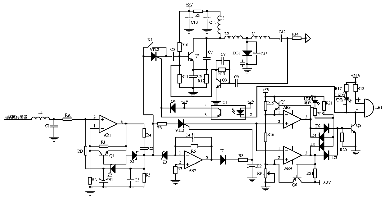
[0012] Embodiment 1, a fault monitoring system for a switch point machine display rod, the voltage corresponding to the gap width signal of the switch point machine display rod detected by the eddy current sensor is processed by the microprocessor module and transmitted to the remote monitoring terminal through the communication module To realize remote monitoring, this application transmits the gap width signal of the turnout switch machine indication rod detected by the eddy current sensor to the remote monitoring terminal after being processed by the signal acquisition unit, the fault discrimination unit, and the signal controllable transmission unit;

[0013] The signal acquisition unit receives the signal of the gap width signal of the turnout switch machine detected by the eddy current sensor. After filtering by LC, it enters the in-phase amplifying circuit composed of operational amplifier AR1, resistor R1, resistor R2, and resistor RA for amplification and conditioning. ...

Embodiment 2

[0014]Embodiment 2, on the basis of Embodiment 1, the signal acquisition unit receives the signal of the gap width signal of the turnout switch machine detected by the eddy current sensor, and after being filtered by the LC filter circuit composed of the inductance L1 and the capacitor C1, it enters the operational amplifier The in-phase amplifier circuit composed of AR1, resistor R1, resistor R2, and resistor RA performs amplification and conditioning. The amplification factor is determined by the resistance values ​​of resistor R1 and resistor RA. The amplified signal is composed of resistor R4, resistor R5, capacitor C2, and capacitor C3. The RC frequency selection circuit selects the frequency, so that the frequency component of the stable DC voltage signal output by the eddy current sensor passes (because the detection module in the prior art only performs half-wave rectification through diode D1 and diode D2, capacitor C5 and capacitor C6 filter , is also the pulsating po...

Embodiment 3

[0015] Embodiment 3, on the basis of Embodiment 1, the fault discrimination unit receives the output signal of the signal acquisition unit, enters the operational amplifier AR3, the transistor Q4, the high threshold voltage (resistance R15, resistance R6, the voltage divider formed by the potentiometer RP1 The hysteresis comparator of the high threshold voltage composed of the circuit provided) judges whether the gap width of the pole is higher than the voltage 2.5+0.8V corresponding to 2+0.5mm, and enters the op amp AR4, transistor Q6, low threshold voltage (resistor R15, resistor R6 , Potentiometer RP1 composed of a voltage divider circuit provided) The low threshold voltage hysteresis comparator judges whether the rod gap width is lower than the voltage 2.5-0.8V corresponding to 2-0.5mm, higher than the low threshold voltage and the low and high thresholds When the voltage is low, the slight interference during high-low level conversion is eliminated, and the two hysteresis ...


PUM


Abstract

The invention discloses a turnout switch machine indication rod fault monitoring system. A signal collecting unit receives a signal of the notch width of a turnout switch machine indication rod detected by an eddy current sensor; the signal is subjected to amplification and conditioning by an in-phase amplifying circuit; and a transistor Q1 is set to reduce an abnormal high potential signal and anelectrolytic capacitor E2 is set to increase an abnormal low potential signal. When there is a tendency of abnormality the signal, the signal enters a fault discriminating unit, and whether the notchwidth of an indication rod is within 2+-0.5mm is judged by a double hysteresis comparator. When the signal is normal, a green indicator light is on. When the signal is abnormal, the red indicator light is on, and a horn alarm is activated. When the time of a timing switch K1 of a signal controllable transmission unit is arrived at or when the abnormality is judged, a signal output by an operational amplifier AR1 is initially subjected to frequency-modulation by an oscillation circuit to generate a high-frequency modulation signal which is further resonating with a resonance circuit to generate an optimal transmission frequency, and then the signal is subjected to frequency selection and fed back to the oscillating circuit. The signal is further stably transmitted to a remote monitoring terminal. The circuit structure is simple, which improves the timeliness of the abnormal information processing.

Description

technical field [0001] The invention relates to the technical field of fault detection, in particular to a fault monitoring system for a switch machine indicating rod. Background technique [0002] The authorized announcement number is CN104197821B. The monitoring system for the notch width of the turnout switch machine and its eddy current sensor uses the movement of metal conductors to change the magnetic field generated by the eddy current probe and convert it into current or voltage, which is rectified and filtered by the detection module. Temperature compensation module temperature compensation, output buffer module amplified output, designed an eddy current sensor that meets the actual needs (accuracy, sensitivity); the eddy current sensor detects the width information of the indication rod gap and transmits it to the collector. The AD acquisition module in the middle is connected to the microprocessor module, and after processing, it is transmitted to the remote monit...

Claims


Application Information

Patent Timeline
IPC IPC(8): B61L5/10G01B7/02B61L27/00
CPCB61L5/10G01B7/02B61L27/53
Inventor 卢伟李春莹李丽兰梁宏伟占雪梅
Owner ZHENGZHOU RAILWAY VOCATIONAL & TECH COLLEGE
Why Eureka
Try Eureka