A K1 type electrical connector assembly for mineral insulated cables for nuclear power

A technology for mineral insulated cables and electrical connectors, which is applied to insulated cables, fixed/insulated contact members, electrical components, etc., and can solve the problems of mechanical strength and dielectric performance decline, easy to absorb moisture, insulation performance, easy to short circuit, etc. Improve sealing reliability and shock resistance, improve aging life and long service life

Active Publication Date: 2021-05-11
CHINA AVIATION OPTICAL-ELECTRICAL TECH CO LTD
View PDF9 Cites 0 Cited by
  • Summary
  • Abstract
  • Description
  • Claims
  • Application Information

AI Technical Summary

Problems solved by technology

[0002] Mineral insulated cables are very different from conventional cables. The sheath of mineral cables is made of stainless steel, and the insulating material between the core wires is silica powder. During the stripping process, silica powder is easy to absorb moisture, resulting in reduced insulation performance. The core wire has no independent insulating layer and is easy to short circuit. Therefore, the integration of mineral cables and electrical connectors is a very complicated technology. However, since mineral cables themselves do not have any organic materials, compared with conventional organic cables, they are more resistant to radiation and high temperature. , long life, corrosion resistance and mechanical strength of the skin have absolute advantages
[0003] The conventionally designed insulating support material for electrical connectors is plastic, but the mechanical strength and dielectric properties of this type of insulating support will decrease to varying degrees under high cumulative doses of radiation and high temperature environments, which may lead to failure of electrical connectors

Method used


Image

  • A K1 type electrical connector assembly for mineral insulated cables for nuclear power
  • A K1 type electrical connector assembly for mineral insulated cables for nuclear power
  • A K1 type electrical connector assembly for mineral insulated cables for nuclear power

Examples


Embodiment Construction

[0049] In order to further illustrate the technical means and technical effects adopted by the present invention, a K1-type electrical connector assembly for nuclear power mineral insulated cables of the present invention will be described in detail below in conjunction with embodiments.

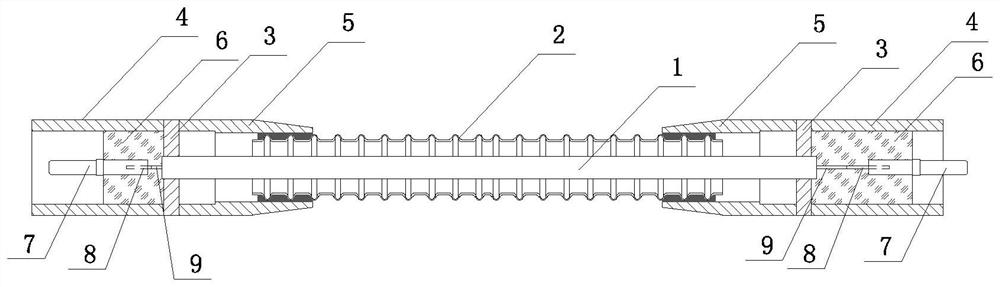
[0050] The present invention includes a cable assembly and plugs and sockets connected to both ends of the cable assembly. The cable assembly includes a mineral cable 1, a stainless steel bellows 2 wrapped outside the mineral cable, a positioning plate 3 for fixing the two ends of the mineral cable, and a positioning plate Stainless steel pipe 4 welded by laser welding. The two ends of the stainless steel bellows are connected with a terminal sleeve 5, and the positioning plate and the terminal sleeve are welded by laser welding, and the stainless steel pipe and the terminal sleeve are respectively located on both sides of the positioning plate. There is at least one mineral cable wrapped in...


PUM

PropertyMeasurementUnit
sizeaaaaaaaaaa

Abstract

The invention relates to a K1 type electrical connector assembly for a mineral insulated cable for nuclear power, comprising a cable assembly, a plug and a socket plugged into both ends of the cable assembly, the cable assembly includes a mineral cable, a corrugated tube wrapped outside the mineral cable, and a The positioning plate for fixing the mineral cable and the stainless steel tube welded with the positioning plate; the stainless steel tube is provided with a glue filling area and a transfer jack contact; the transfer jack contact is a double-ended jack structure, one end of which is connected to Mineral cable core wires are electrically connected, and the other end is mated with a plug or socket; the plug includes a connecting nut, a splined housing, an insulator part, and a glass sintered part mated with a double-ended socket contact; the socket consists of a socket housing, The glass cake II and the double-head pin contact II are made into an integrated structure through glass sintering; the invention is resistant to radiation, aging, and has a long service life. Remains usable after severe accident conditions.

Description

technical field [0001] The invention relates to the technical field of connectors, in particular to a K1 electrical connector assembly for mineral insulated cables for nuclear power. Background technique [0002] Mineral insulated cables are very different from conventional cables. The sheath of mineral cables is stainless steel, and the insulating material between the core wires is silica powder. During the stripping process, silica powder is easy to absorb moisture and cause insulation performance to decrease. The core wire has no independent insulation layer and is easy to short circuit. Therefore, the integration of mineral cables and electrical connectors is a very complicated technology. , long life, corrosion resistance and mechanical strength of the skin have absolute advantages. [0003] The insulating support material conventionally designed for electrical connectors is plastic, but the mechanical strength and dielectric properties of this type of insulating suppo...

Claims


Application Information

Patent Timeline
Patent Type & Authority Patents(China)
IPC IPC(8): H01R13/02H01R13/40H01R13/502H01R4/02H01R13/504H01R13/52H01R13/533H01R31/06H01B7/28H01B7/282H01B7/29
CPCH01B7/2806H01B7/2825H01B7/292H01R4/021H01R4/023H01R13/02H01R13/40H01R13/502H01R13/504H01R13/52H01R13/521H01R13/533H01R31/06
Inventor 顾玲童江浪薛欢欢邵明坤时兴波牛志军杜俊伟赵鹏坤秦海强
Owner CHINA AVIATION OPTICAL-ELECTRICAL TECH CO LTD
Why Eureka
Try Eureka