
Wireless power supply device and wireless power supply system for electric equipment

A wireless power supply and wireless technology, used in circuit devices, electric vehicle charging technology, charging stations, etc., can solve the problems of low energy conversion efficiency, crowding of payloads, high cost of connection point failure risks, etc., to improve energy transfer efficiency. , reduce cost and failure rate, avoid the effect of energy transfer efficiency

Inactive Publication Date: 2019-10-25
胡家兴
View PDF9 Cites 3 Cited by
  • Summary
  • Abstract
  • Description
  • Claims
  • Application Information

AI Technical Summary

Problems solved by technology

[0004] There are some deficiencies in the electric energy supply scheme of the above-mentioned trams, such as the flash charging energy supply technology at the station, because the energy density of the supercapacitor battery suitable for flash charging is too low, so the low-floor trams for this application generally have a huge installation on the top of the car body. Complex composite battery packs take up a lot of space and occupy the payload (usually weighing several hundred kilograms) and cause the vehicle's center of gravity to be high. The impact brought by the power grid and the super-large current during charging (up to 1500A~2400A or even higher current within 20~30 seconds) will cause high temperature to accelerate the aging of insulation parts, all of which require additional investment and continuous maintenance costs. Even if the road is delayed for too long, the air conditioner must be disabled even in summer, and even if the power is exhausted, roadside assistance must be sought. These are not good user experiences; The risk of health injury brought by infants, pregnant women and certain people who have installed cochlear implants or cardiac pacemakers needs to be carefully controlled. Therefore, the power supplement mode of in-stop flash charging brings many challenges to the beauty of the city; for The ground segmental power-taking scheme of the current technology, whether it is the magnetic attraction of the vehicle in place or the electric signal triggering the power supply for partial power supply, the abrasion caused by the friction of the collector shoe, the complex structure inside the conductive module, and the massive connection points. The risk of failure brings higher costs and puts pressure on the builder and operator
The current wireless power supply technology for trams solves the wear problem of the "conductive channel" of other ground power supply technologies. However, because the tram needs to travel at a higher speed, the density of coil or electrode plate dislocation stacking is directly related to the implementation cost and charging efficiency. Massive coils Or the high cost and failure rate caused by electrode plates and electrical contacts and the low energy conversion efficiency are relatively obvious shortcomings
[0005] Patent CN201610200989, a segmented non-contact power supply sending device for rail cars and its control method and patent CN201710616873, an electric field coupled mobile power supply system for rail transit provides another idea of ​​power supply for trams in progress, and its advantages The "power supply module" is static after construction, but its challenge is that the former scheme is more complicated and the implementation cost is relatively high, and the latter will cause stability problems due to changes in climate conditions
[0006] In the field of electric vehicles, contact charging is currently the mainstream, but it is strictly forbidden to use it outdoors on rainy days, which brings inconvenience to people's travel. In addition to the cost of secondary purchase of batteries, the lack of convenient charging facilities is the key to the success of the electric vehicle industry. Reasons, but if there are many charging piles in each parking lot, it must be a big spoiler
Therefore, setting up wireless charging facilities for parking indoors and outdoors, making full use of the parking time of the vehicle, not needing to deliberately operate the charging plug, and the wireless charging mode that can be turned on and charged all day long is the most basic form of electric vehicle power supplement in the future; and the surrounding electromagnetic The wireless charging solution with the least environmental impact and the highest charging efficiency is that the receiving coil or electrode plate at the bottom of the vehicle in each parking space is in close contact with the charging coil or electrode plate installed on the ground. The current technology needs to rely on the repeated use of the vehicle to achieve this goal. Move to face, or move the movable "charging pad" to face the vehicle's power receiving coil or electrode plate, this kind of experience cannot actually be promoted
In order to solve this problem, as disclosed in the patent No. CN201580064426 "Method and System for Operating a Charging Station that Inductively Transfers Electric Energy to a Vehicle with an Accumulator", it is hoped that the vehicle will be parked roughly in place by setting a redundant The coil or electrode plate and a series of electronic adjustment methods to obtain a "reasonable charging position" lead to the complexity and waste of the coil or electrode plate and the circuit

Method used


Image

  • Wireless power supply device and wireless power supply system for electric equipment
  • Wireless power supply device and wireless power supply system for electric equipment
  • Wireless power supply device and wireless power supply system for electric equipment

Examples


Embodiment Construction

[0069] In order to enable those skilled in the art to better understand the present invention, the present invention will now be further described in conjunction with the accompanying drawings and specific implementation cases. Obviously, examples are not intended to limit the present invention.

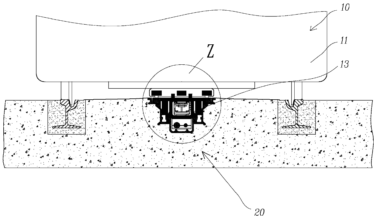
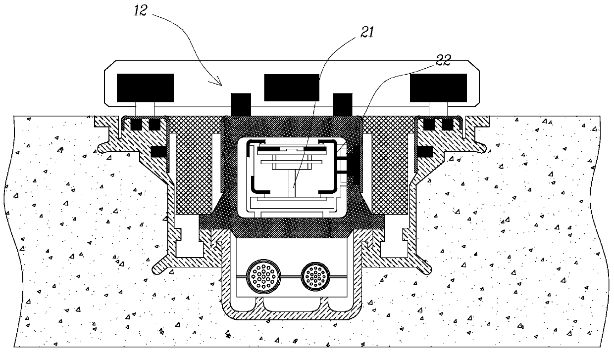
[0070] refer to Figure 1a with Figure 1b , this is the current technology ground segmented magnetic drive direct power supply scheme for trams, and it is also an application of patent CN201310712092. The figure is a cross-sectional view of practical application. A magnet is provided on the bottom side of the collector shoe 13; a segmented power supply module 20 slightly higher than the track is buried on the ground between the rails, and an elastic element 21 with magnetic displacement is arranged inside, so that there is always electricity inside the module, when the carriage 10 After reaching a certain position, the magnet drives the elastic element 21 to move up, and the interna...


PUM


Abstract

The invention discloses a wireless power supply device and a wireless power supply system for electric equipment. During the electromagnetic field or electric field coupling of wireless transmission of electric energy, matching opposite property of a power supplying-receiving coil is very extremely sensitive to the transmission efficiency of electric energy. A power supply end of a tramcar is composed of rail lines and a mobile power supply block, wherein the rail lines are connected with a power supply and are arranged in sealed pipelines on the ground between rails below the bottom of the tramcar, the mobile power supply block is connected with the rail lines and opposite to a current collecting shoe on the outer side of a sealed body wall through magnetic attraction, and the effects that the mobile power supply block which is always opposite to the power supplying-receiving coil advances along with the tramcar synchronously and provides close-range wireless power supply in real timeare formed; the configuration amount of energy storage batteries of the tramcar can be reduced when the real-time power supply electric energy is directly consumed in tramcar movement, thereby savingcost, space and weight, enhancing space utilization effectiveness, aesthetic degree and movement efficacy, and having great comprehensive value; and through marking and positioning a power supply coil when the electric vehicle is being charged, a power receiving coil automatically corrects position by means of an alignment mechanism, thus energy transmission efficiency is improved, and a foundation is laid for implementing a simple and beautiful parking lot and acquiring all-weather non-contact charging for outdoor parking spaces.

Description

technical field [0001] The invention belongs to the technical field of energy supply or supplement for electric vehicles or equipment, and specifically relates to a wireless power supply device, a traveling power supply system for trams and a static charging system for mobile machines using the device. Background technique [0002] In recent years, in the city, people need to travel conveniently, hope the city is beautiful, and the air is clean, but the large-scale use of fuel private cars has brought traffic congestion and exhaust pollution. Alleviating these contradictions requires a multi-pronged approach. At the level of transportation and energy technology, it is necessary to vigorously develop public transportation and vehicle energy oil to electricity. Each city builds various types of public transportation according to its own scale and development expectations, such as building large-capacity The subway system operating underground in the city, the street rail syste...

Claims


Application Information

Patent Timeline
Patent Type & Authority Applications(China)
IPC IPC(8): H02J50/90H02J50/10B60M3/00B60L53/12B60L53/38B60L53/126
CPCH02J50/10H02J50/90B60M3/00Y02T90/16Y02T90/12Y02T10/70Y02T90/14Y02T10/7072
Inventor 胡家兴
Owner 胡家兴
Learn More