

Ultra-thin plasmonic solar cells, methods for their manufacture and use
A solar cell and plasma technology, which is applied in semiconductor/solid-state device manufacturing, final product manufacturing, sustainable manufacturing/processing, etc., and can solve problems such as metal nanoparticles and plasma solar cells that are not considered
- Summary
- Abstract
- Description
- Claims
- Application Information
AI Technical Summary
Problems solved by technology
Method used
Image

Examples
specific Embodiment approach
[0107] According to a first aspect, the present invention provides a solar cell comprising:
[0108] - an n-type semiconductor layer;
[0109] - a layer of metal nanoparticles selected from the group consisting of copper, gold, silver or aluminum; and
[0110] - a p-type semiconductor layer,
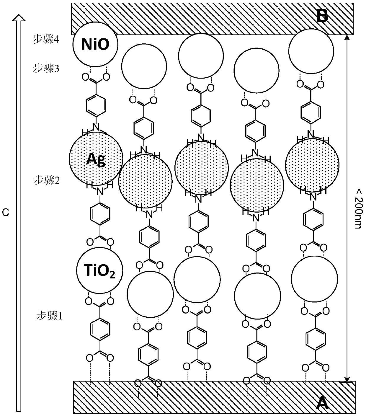
[0111] The above-mentioned layers are sandwiched between the substrate and the back contact; wherein the substrate, n-type semiconductor, metal nanoparticles, p-type semiconductor and back contact are respectively connected by covalent bonds by means of one or more molecular linkers.
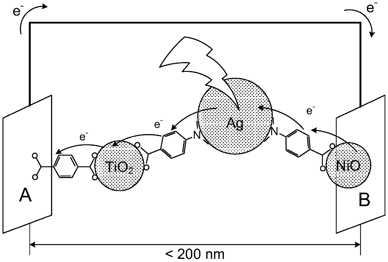
[0112] The fundamentals of ultrathin plasmonic solar cells are figure 1 shown in . Such cells are based on localized surface plasmon (LSP) resonance of silver (Ag) nanoparticles used as light absorbers. This is covalently attached to TiO on one side with the aid of 4-aminobenzoic acid (pABA) as a molecular linker 2 (electron acceptor) and on the other side covalently linked to NiO (hole acceptor). I...
example 1
[0203] Example 1. Synthesis of metal nanoparticles
[0204] From corresponding metal precursors such as but not limited to AgNO 3 、CuSO 4 , CuCl 2 or HAuCl 4 , reducing agent and stabilizer to start the synthesis of gold, silver and copper metal nanoparticles. Examples of reducing agents include NaBH 4 , N 2 h 4 , ascorbic acid, betaine, polyols (such as ethylene glycol, diethylene glycol, triethylene glycol, tetraethylene glycol polyethylene glycol). Examples of stabilizers or growth limiting agents include betaines, polyvinylpyrrolidone, polyvinyl acetate, polyols (eg, ethylene glycol, diethylene glycol, triethylene glycol, tetraethylene glycol polyethylene glycol). All reagents were purchased from Sigma-Aldrich / Merck and were of analytical quality.
[0205] The inventors followed the protocol proposed by Dong et al. 2015, which is incorporated herein by reference, varying selected parameters such as component concentrations, solvents, reaction temperature and reac...
example 2
[0210] Example 2. Semiconductor Nanoparticles
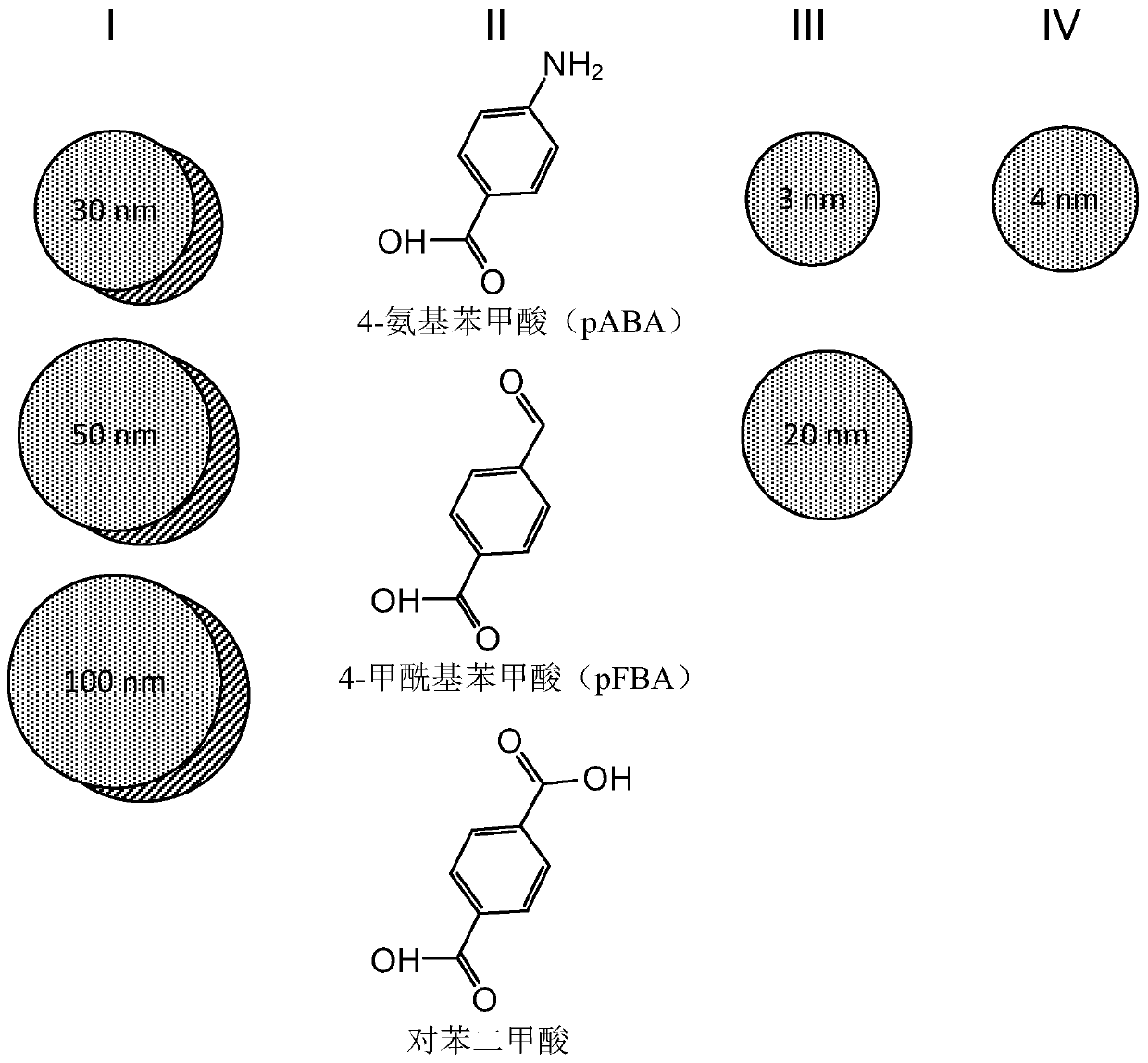
[0211] NiO remains one of the best p-type semiconductors, making it the preferred choice for proof-of-concept devices. NiO nanoparticles were synthesized using the following method: Ni(II) acetylacetonate was dissolved in oleylamine and heated to 110°C under vigorous stirring, and then cooled to and kept at 90°C. Next, the borane-triethylamine complex mixed with oleylamine was rapidly injected into the solution at 90 °C and allowed to stand under vigorous stirring for 1 hour. The NiO nanoparticles were then washed with ethanol and finally dispersed in n-tetradecane. This procedure produces particles of approximately 4 nm in diameter. Anatase, a TiO with a particle size of 3 nm and 20 nm, was obtained from Sachtleben Chemie GmbH, Duisburg, Germany 2 Nano powder.
PUM
| Property | Measurement | Unit |
|---|---|---|
| thickness | aaaaa | aaaaa |
| thickness | aaaaa | aaaaa |
| thickness | aaaaa | aaaaa |
Abstract
Description
Claims
Application Information