An active clamp flyback converter and its control method

A technology of flyback converter and control method, applied in control/regulation system, DC power input conversion to DC power output, instrument, etc., can solve the problem of failure to realize zero voltage turn-on, increase on-state loss, and affect the service life of devices and other problems to achieve the effect of avoiding the reverse surge of excitation current, improving circuit EMI, and improving work efficiency

Active Publication Date: 2020-09-15
MORNSUN GUANGZHOU SCI & TECH
View PDF4 Cites 0 Cited by
  • Summary
  • Abstract
  • Description
  • Claims
  • Application Information

AI Technical Summary

Problems solved by technology

However, when the output clamp of the secondary side is lost, the voltage Vds_S1 waveform at both ends of the drain and source of the main switch tube S1 oscillates, which affects the EMI of the system. At the same time, the clamp tube S2 also fails to achieve zero-voltage turn-on, which increases the switching loss.
[0007] To sum up the above, although the non-complementary control strategy solves the problem of the reverse surge of the traditional complementary active-clamp flyback circuit that enters the intermittent operation mode with high input voltage, the excitation current and leakage inductance current on the primary side of the transformer lose the output clamp on the secondary side. , but it also introduces oscillation, and the clamp tube does not achieve ZVS, which increases the switching loss
The non-complementary control strategy itself also has problems, because the process of storing energy from the leakage inductance Lk to the clamp capacitor Cr does not turn on the clamp switch S2, resulting in all the high-frequency current flowing through the body diode of the clamp switch S2
Usually, the reverse recovery characteristics of the body diode are poor, and the rapid current change rate will lead to an increase in the reverse recovery current of the body diode of the clamp switch S2. The reverse recovery of the body diode not only affects the service life of the device, but also increases the on-state loss, reducing the circuit efficiency
For the active clamp flyback converter in continuous operation mode at low input voltage, compared with the complementary control strategy, the non-complementary control strategy has many disadvantages

Method used


Image

  • An active clamp flyback converter and its control method
  • An active clamp flyback converter and its control method
  • An active clamp flyback converter and its control method

Examples


no. 1 example

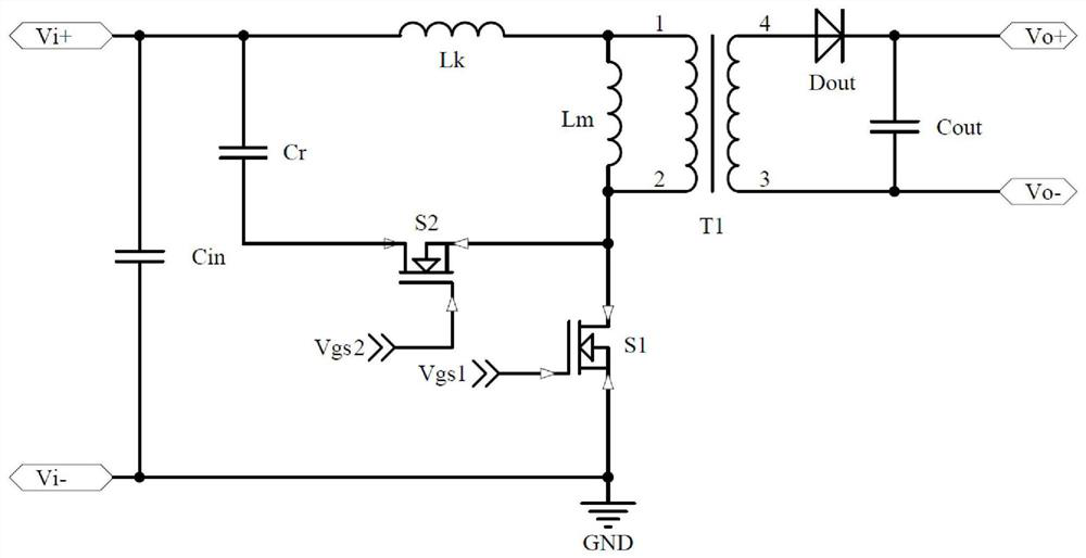
[0030] Figure 5 Shown is a schematic diagram of an active clamp flyback converter implemented by the present invention. The circuit includes a main power circuit, a main clamp circuit, an auxiliary clamp circuit and an output rectifying and filtering circuit. Among them, the main power circuit is formed by connecting the transformer T1 and the main switching tube S1; the main clamping circuit is formed by connecting the main clamping switching tube S2 and the main clamping capacitor Cr; the auxiliary clamping circuit is composed of the auxiliary clamping switching tube S3, the auxiliary clamping The clamping capacitor Cc is formed by connecting the auxiliary clamping diode Dc; the output rectification filter circuit is formed by connecting the output rectifying diode Dout and the output capacitor Cout. The detection method to determine the working state of the circuit adopts the method of comparing the detected input voltage with the set input voltage threshold; the input vol...

no. 2 example

[0057] The schematic diagram of the active clamp flyback converter is the same as that of Embodiment 1. The difference between this embodiment and the first embodiment is that in the driving mode 1 of the second embodiment, the main clamp tube S2 and the auxiliary clamp switch tube S3 are connected to The main switching tube S1 is in a complementary driving state. Therefore, this embodiment only provides the working principle of the driving mode 1.

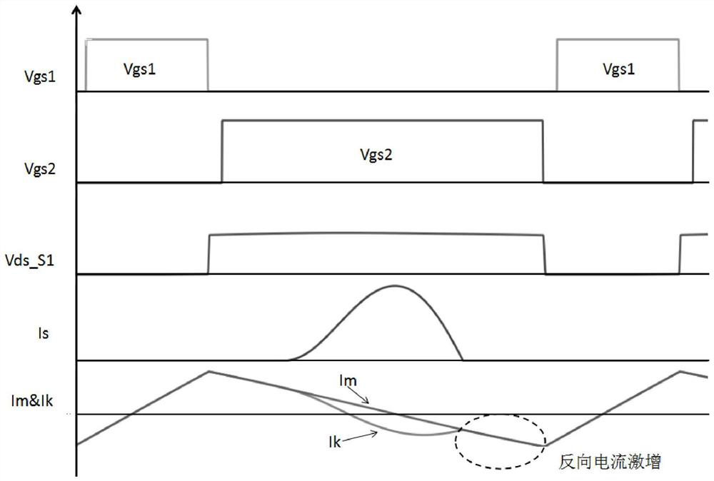
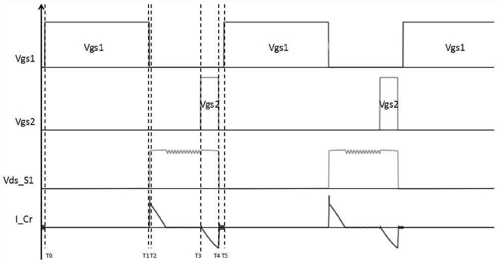
[0058] When the input voltage is lower than the set threshold, the circuit is in a continuous working state. At this time, the driving mode 1 is adopted. At this time, the auxiliary clamping switch S3 is in the non-working state, and the main clamping tube S2 and the main switching tube S1 are in the complementary driving state. . Figure 8 The working waveform diagram is shown, in which Vgs1 is the driving waveform of the main switching tube S1, Vgs2 is the driving waveform of the main clamping switching tube S2, Vds_S1 is the v...


PUM


Abstract

The invention discloses an active clamp flyback converter and a control method thereof, comprising a main power circuit, a main clamp circuit, an auxiliary clamp circuit and an output rectifying and filtering circuit; wherein, the main power circuit consists of a transformer and a main switching tube The main clamping circuit is formed by connecting the main clamping switch tube and the main clamping capacitor; the auxiliary clamping circuit is formed by connecting the auxiliary clamping switch tube, auxiliary clamping capacitor and auxiliary clamping diode; the output rectification filter The circuit is formed by connecting the output rectifier diode and the output capacitor; in the continuous working state, the driving mode is: the main clamping switch tube and the main switching tube are complementary driven, and the auxiliary clamping switch tube is not driven; in the intermittent working state, the driving mode is The mode is: the main clamp switch tube and the main switch tube are driven non-complementarily, and the auxiliary clamp switch tube and the main switch tube are driven complementary. Compared with the prior art, the invention has a wide input voltage range, realizes zero-voltage turn-on of all switch tubes, improves circuit working efficiency, and improves circuit EMI.

Description

technical field [0001] The present invention relates to the field of switching converters, in particular to an active clamp flyback converter; the present invention also relates to a control method for the active clamp flyback converter. Background technique [0002] With the rapid development of the field of power electronics, switching converters are used more and more widely. People place more demands on switching converters: high power density, high reliability and small size. Generally, the traditional AC / DC conversion is realized by the flyback topology, which has the advantages of simple structure and low cost. In the actual working process, due to the existence of leakage inductance, the flyback converter often needs RCD clamping circuit, LCD clamping circuit or active clamping circuit as the absorption circuit. Among them, the flyback converter with an active clamp snubber circuit can not only absorb the leakage inductance energy, but also feed back the leakage in...

Claims


Application Information

Patent Timeline
Patent Type & Authority Patents(China)
IPC IPC(8): H02M3/335H02M1/088H02M1/44
CPCH02M1/088H02M1/44H02M3/33569H02M1/0058Y02B70/10
Inventor 尹向阳马守栋钟天明王志燊
Owner MORNSUN GUANGZHOU SCI & TECH
Why Eureka
Try Eureka