Oil stain treatment system based on Internet of Things

An Internet of Things technology and treatment system technology, applied in the field of oil pollution treatment, can solve the problems of low oil pollution treatment effect, lack of intelligent and macroscopic management, etc., achieve the effect of saving water and ensuring the effect of cleaning pollution

Inactive Publication Date: 2019-12-13
南京庞瑞科技有限公司
View PDF7 Cites 1 Cited by
  • Summary
  • Abstract
  • Description
  • Claims
  • Application Information

AI Technical Summary

Problems solved by technology

[0004] The purpose of the present invention is to provide an oil pollution treatment system based on Internet of Things technology in order to solve the problem that the existing oil pollution treatment effect is not high, and the management lacks intelligence and macroscopicity at the same time

Method used


Image

  • Oil stain treatment system based on Internet of Things
  • Oil stain treatment system based on Internet of Things
  • Oil stain treatment system based on Internet of Things

Examples


Embodiment 1

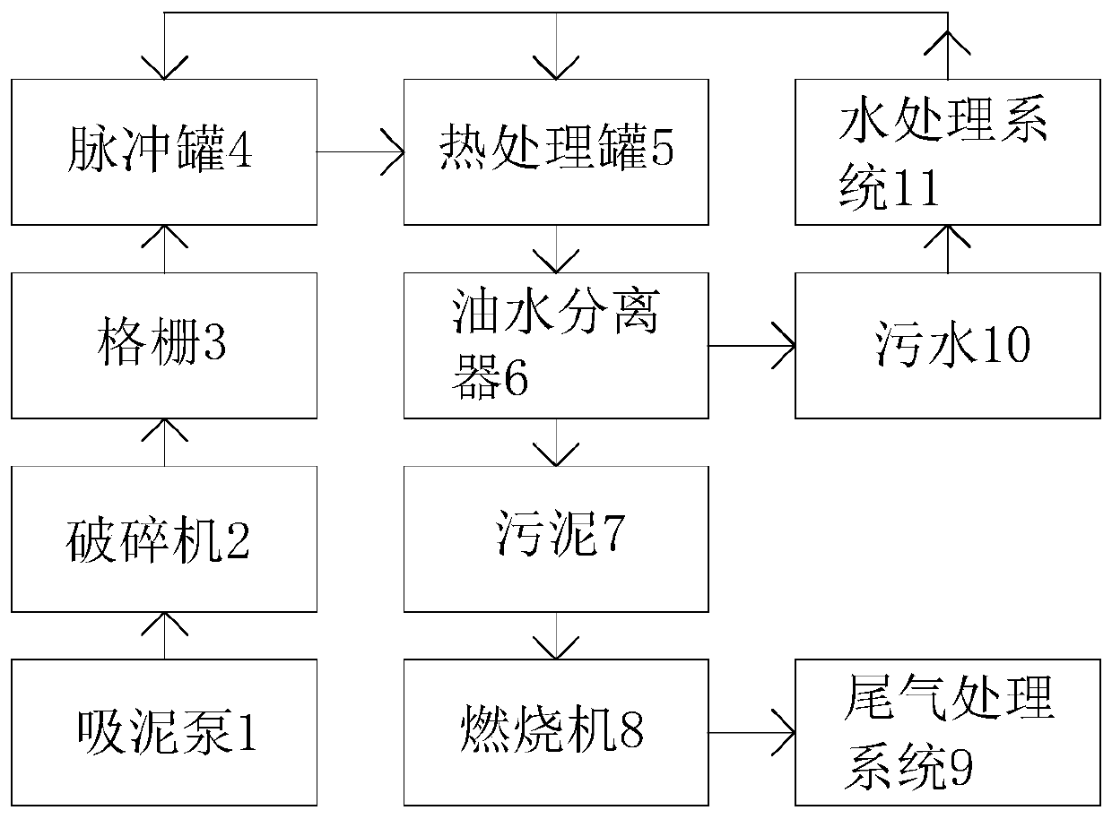
[0026] Example 1, please refer to figure 1 and 3 ~4. An oil pollution treatment system based on the Internet of Things technology, including an oil pollution treatment system and an intelligent monitoring and management system;

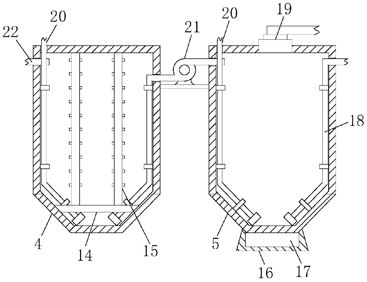
[0027] The oil pollution treatment system includes a dredge pump 1, a crusher 2, a grid 3, an impulse tank 4, a heat treatment tank 5, an oil-water separator 6, a burner 8 and an exhaust gas treatment system 9 connected in sequence, and the oil-water separator 6 The separated sludge 7 enters the burner 8, and the separated sewage 10 enters the water treatment system 11. The water treatment system 11 is connected with the pulse tank 4 and the heat treatment tank 5 through the flushing pipe 20. The left side of the pulse tank 4 is installed There is a sewage inlet pipe 22, the heat treatment tank 5 is located on the right side of the pulse tank 4, an extraction pump 21 is arranged between the pulse tank 4 and the heat treatment tank 5, and the two ends...

Embodiment 2

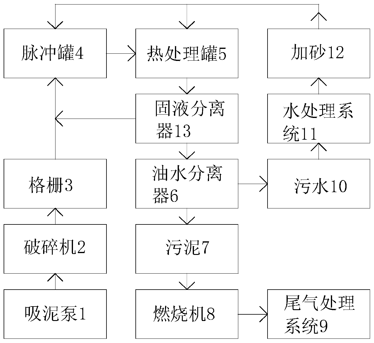
[0029] Example 2, please refer to Figure 2-4 , an oil pollution treatment system based on Internet of Things technology, including an oil pollution treatment system and an intelligent monitoring and management system;

[0030]The oil pollution treatment system includes a dredge pump 1, a crusher 2, a grid 3, an impulse tank 4, a heat treatment tank 5, a solid-liquid separator 13, an oil-water separator 6, a burner 8 and an exhaust gas treatment system 9 connected in sequence, The solid-liquid separator 13 is connected with the pulse tank 4 at the same time, the sludge 7 separated by the oil-water separator 6 enters the burner 8, and the separated sewage 10 enters the water treatment system 11, and the water treatment system 11 passes through the flushing pipe 20 is connected with the pulse tank 4 and the heat treatment tank 5, and a sanding 12 is also provided between the water treatment system 11, the pulse tank 4 and the heat treatment tank 5, and the sewage inlet pipe 22 i...


PUM


Abstract

The invention discloses an oil stain treatment system based on Internet of Things. The system comprises an oil strain treatment system and an intelligent monitoring and management system, wherein theoil stain treatment system comprises a sludge sucking pump, a crushing machine, grids, a pulse tank, a thermal treatment tank, an oil-water separator, a combustor and a tail gas treatment system whichare connected in sequence; sludge separated by using the oil-water separator is fed into the combustor; separated sewage is fed into a water treatment system; the water treatment system is connectedwith the pulse tank and the thermal treatment tank through a flashing tube; a dirt feeding tube is mounted on the left side of the pulse tank; and the thermal treatment tank is positioned on the rightside of the pulse tank. By adopting the oil strain treatment system, oil stain is subjected to pulse treatment, emulsified oil stain can be broken through electromagnetic pulse, meanwhile oil, waterand sludge are subjected to ionization, then separation of oil, sludge and water can be facilitated, and situations that the separation effect is poor and waste dregs after separation still contain agreat amount of sump oil in later separation as emulsified and coagulated sump oil in oil stain is hard to break at present can be solved.

Description

technical field [0001] The invention belongs to the technical field of oil pollution treatment, in particular to an oil pollution treatment system based on Internet of Things technology. Background technique [0002] At present, a large amount of oily sludge is produced in our country every year. The specific characteristics of oily sludge are as follows: high oil content and high viscosity; complex components and difficult treatment; most harmful components exceed the emission standards; and contain high calorific value. Due to the large volume of oily sludge, which contains a large amount of mineral oil, sulfide, benzene series, phenols, anthracene, pyrene and other toxic and harmful substances with odor, oily sludge is classified as HW08 hazardous waste. In actual production, four treatment methods are mainly used in China: (1) cracking method, with less processing capacity, high energy consumption, high cost, and high risk. Dioxin, carbon dioxide and other gases will be ...

Claims


Application Information

Patent Timeline
Patent Type & Authority Applications(China)
IPC IPC(8): C02F11/00C02F11/13C02F11/15C02F11/18C02F1/40
CPCC02F1/40C02F11/00C02F11/006C02F11/13C02F11/15C02F11/18
Inventor 郭志
Owner 南京庞瑞科技有限公司
Why Eureka
Try Eureka