
A method for removing and recovering copper in copper-containing molten iron

A technology for recovering copper, copper and iron, which is applied in the field of iron and steel metallurgy, can solve problems such as difficulty in guaranteeing process continuity and stability, decline in decopper ability, high equipment requirements, etc., to achieve directional mass transfer and enrichment, equipment and environment The effect of low requirements and simple process operation

Active Publication Date: 2021-09-07
NORTHEASTERN UNIV LIAONING
View PDF34 Cites 0 Cited by
  • Summary
  • Abstract
  • Description
  • Claims
  • Application Information

AI Technical Summary

Problems solved by technology

Among the existing methods, the gasification evaporation method has high requirements for equipment and processing environment; the ceramic filtration method is limited by the erosion and corrosion of high-temperature molten iron, and the continuity and stability of the process are difficult to guarantee
In comparison, the sulfide slag method is a treatment method that can be applied to the decoppering of molten iron, but at present, the method also has the problem that the distribution ratio of copper between slag and gold is low when the sulfide slag system is decoppered, and a larger slag is required. The decoppering effect of this method is guaranteed, and the decoppering ability of the slag system drops significantly in the later stage of decoppering, which cannot meet the needs of deep decoppering in iron. The decoppering efficiency of this method, especially the decoppering efficiency in the later stage, still needs to be further improved

Method used


Image

  • A method for removing and recovering copper in copper-containing molten iron
  • A method for removing and recovering copper in copper-containing molten iron

Examples


Embodiment 1

[0050] In this embodiment, the molten iron containing 5wt% Cu is subjected to the de-Cu treatment of the sulfide slag system and the DC electric field, and the specific steps are as follows:

[0051] (1) Preparation of copper removal slag system: for the molten iron environment, preparation of FeS-Na 2 S binary sulfide slag system, prepare 100g decopper slag system at a molar ratio of 2:8.

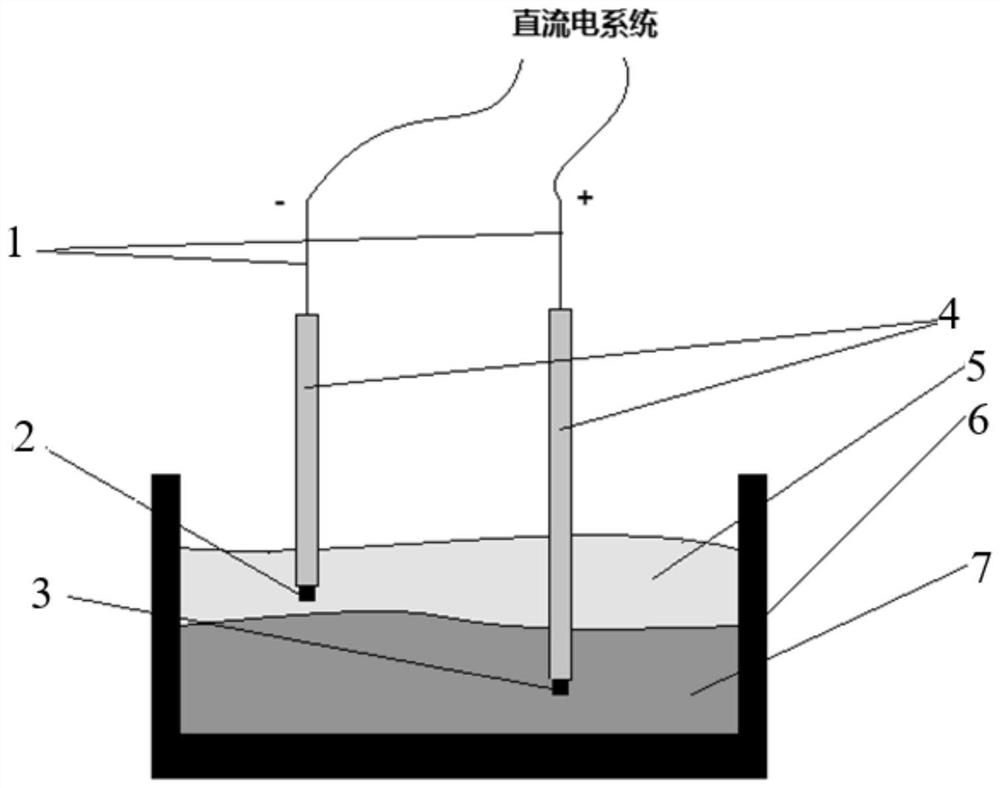
[0052] (2) Copper removal from sulfide slag: 380g of pig iron is crushed and mixed with 20g of pure copper particles, put into figure 1 The electrolytic cell 7 in the present invention does not limit the material structure and type of the electrolytic cell 7, as long as it meets the functions of insulation and holding slag iron at high temperature. In a heating furnace under the protection of an inert gas, raise the temperature of iron slag to 1300°C and melt it, then add the sulfide decopper slag system prepared in step (1). The type of inert gas is not limited, preferably argon.

[005...


PUM


Abstract

The invention relates to a method for removing and recovering copper in copper-containing molten iron, comprising steps: S1: preparing a decopper molten salt slag system: mixing FeS and MS to obtain a decopper molten salt slag system; the M is One or more selected from Na, K, Li, Ba, Sr and La; S2: decopper reaction: put the decopper molten salt slag into copper-containing iron liquid for decopper reaction, and the temperature of copper-containing iron liquid is 1300‑1500°C, the mass ratio of decopper molten salt slag to copper-containing molten iron is 1:4‑2:1; the decopper reaction includes the reaction formula: FeS+Cu=Cu 2 S+Fe; generated Cu 2 S is dissolved in MS to form a sulfide molten salt electrolyte; S3: Applying a DC electric field to strengthen decopper: insert the cathode into the sulfide molten salt electrolyte, insert the anode into the molten iron, and apply a DC electric field between the cathode and the anode; the voltage is 0.2 V‑2V, current density at 0.05A / cm 2 Above, the power-on treatment time is not less than 30min; the electrode reaction is: cathode: 2Cu + +2e ‑ = Cu, anode: S 2‑ -2e ‑ =S; S4: Separation of decopper molten iron and sulfide molten salt slag system: take out the electrode after power off, separate sulfide molten salt electrolyte from molten iron, and obtain copper-containing sulfide molten salt slag system and decopper molten iron.

Description

technical field [0001] The invention relates to the technical field of iron and steel metallurgy, in particular to a method for deep decoppering of copper-containing molten iron and recovery of copper resources. Background technique [0002] For most steel types, copper is a major residual element, which remains in the steel, which can easily cause grain boundary weakening, induce hot embrittlement, cracks and other defects during processing, and will also seriously affect the deep drawing of steel. performance and plating performance. Copper mainly comes from co-associated iron ore and scrap steel. With the development of comprehensive utilization technology of co-associated iron ore resources and the continuous increase in the amount of scrap steel in the society, the actual demand for increasing the scrap steel into the furnace during the smelting process increases, and a large amount of copper enters the iron-based melt, which affects the performance of high-quality ste...

Claims


Application Information

Patent Timeline
Patent Type & Authority Patents(China)
IPC IPC(8): C25D21/18C25C3/34
CPCC25C3/34C25C7/025
Inventor 刘承军陆志豪姜茂发
Owner NORTHEASTERN UNIV LIAONING
Learn More