
Coil self-excitation-based ferromagnetic pipeline electromagnetic ultrasonic transducer, excitation device and receiving device

An electromagnetic ultrasonic and ferromagnetic technology, which is applied in measuring devices, ultrasonic/sonic/infrasonic generation, material analysis using sound/ultrasonic/infrasonic, etc. It can solve the problem of large probe volume, low ultrasonic excitation efficiency, and unsuitable for small size. The requirements of modernization and portability, etc., achieve the effect of reducing volume and simple structure

Inactive Publication Date: 2019-12-13
XIAMEN UNIV
View PDF8 Cites 5 Cited by
  • Summary
  • Abstract
  • Description
  • Claims
  • Application Information

AI Technical Summary

Problems solved by technology

[0008] However, the electromagnetic ultrasonic transducers currently used for pipeline defect detection mainly have the following deficiencies: First, the electromagnetic ultrasonic transducers mostly use the Lorentz force effect for excitation, while the online pipelines are mostly ferromagnetic pipes, so the efficiency of ultrasonic excitation is not high. Second, the electromagnetic ultrasonic transducers all use rigid magnets to provide the bias magnetic field, and the probe is large in size, which is not suitable for the miniaturization and portability of the electromagnetic ultrasonic transducer for pipeline defect detection.

Method used


Image

  • Coil self-excitation-based ferromagnetic pipeline electromagnetic ultrasonic transducer, excitation device and receiving device
  • Coil self-excitation-based ferromagnetic pipeline electromagnetic ultrasonic transducer, excitation device and receiving device
  • Coil self-excitation-based ferromagnetic pipeline electromagnetic ultrasonic transducer, excitation device and receiving device

Examples


Embodiment 1

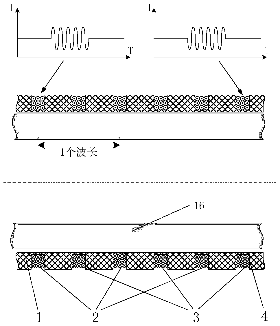
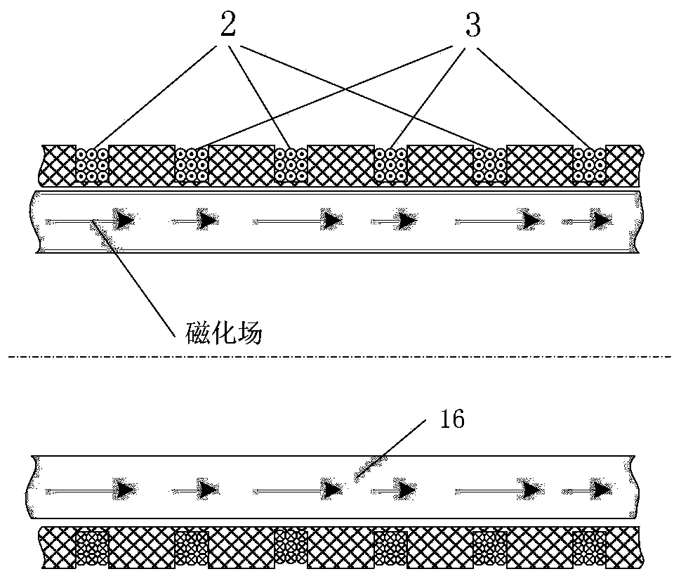
[0042] see figure 1 , which is a structural schematic diagram of Embodiment 1 of the present invention, provides a ferromagnetic tube electromagnetic ultrasonic transducer with coil self-excitation, including: a skeleton 1, a normal-phase coil group 2, and an anti-phase coil group 3, wherein,

[0043] Skeleton 1 is a hollow cylindrical tube of insulating material, its inner diameter is slightly larger than the outer diameter of the ferromagnetic pipeline to be tested, and is coaxially sleeved on the outer surface of the pipeline. On the upper surface of the frame 1, there are 6 annular wire slots 4 at equal intervals; the distance between the wire slots 4 is 5mm, which is 1 / 2 of the wavelength of the excited ultrasonic waves.

[0044] The positive-phase coil group 2 is composed of 3 positive-phase coils connected in series; the normal-phase coil is a ring coil; the number of turns of each positive-phase coil is 9 turns, and the copper enameled wire with a diameter of Ф1 mm is ...

Embodiment 2

[0052] see Figure 5 , which is a structural block diagram of Embodiment 2 of the present invention, provides a coil self-excited ferromagnetic pipeline electromagnetic ultrasonic excitation device, including: electromagnetic ultrasonic transducer 5, high-power constant current source 6, pulse signal source 7, reverse phase Device 8, non-phase power amplifier 9, inverting power amplifier 10, isolation capacitor 11, wherein,

[0053] The electromagnetic ultrasonic transducer 5 is a coil self-excited ferromagnetic pipeline electromagnetic ultrasonic transducer provided in Embodiment 1, which is installed on the ferromagnetic pipeline 16 to be tested;

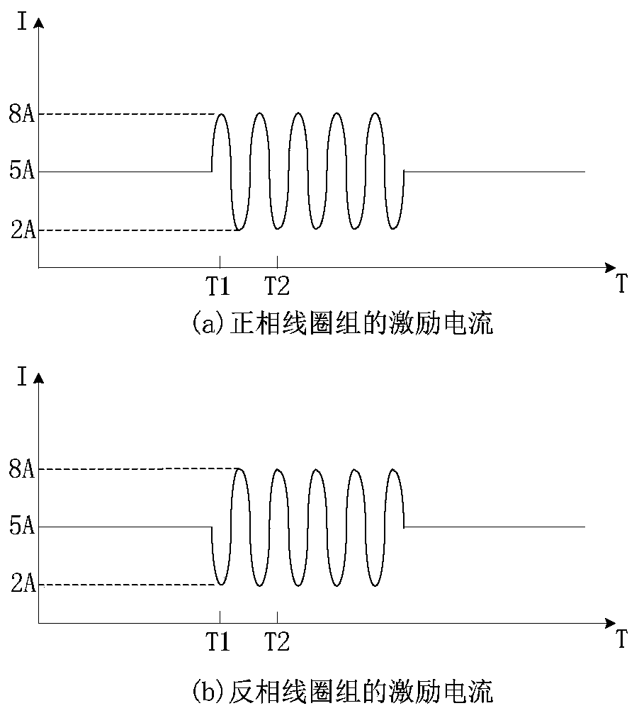
[0054] The high-power constant current source 6 is preferably EPS-3020MD constant current source current to generate two 5A DC bias currents; the first output is connected to the positive phase coil group 2 of the electromagnetic ultrasonic transducer 5, and the second output is connected to the electromagnetic ultrasonic The ant...

Embodiment 3

[0062] see Image 6 , which is a structural block diagram of Embodiment 3 of the present invention, provides a coil self-excitation ferromagnetic pipeline electromagnetic ultrasonic receiving device, including: electromagnetic ultrasonic transducer 5, high-power constant current source 6, coupling capacitor 12, signal conditioning circuit 13, acquisition circuit 14, host computer 15, wherein,

[0063] The electromagnetic ultrasonic transducer 5 is a coil self-excited ferromagnetic pipeline electromagnetic ultrasonic transducer provided in Embodiment 1, which is installed on the ferromagnetic pipeline 16 to be tested;

[0064] The high-power constant current source 6 is preferably EPS-3020MD constant current source current to generate two 5A DC bias currents; the first output is connected to the positive phase coil group 2 of the electromagnetic ultrasonic transducer 5, and the second output is connected to the electromagnetic ultrasonic The anti-phase coil group 3 of the tran...


PUM


Abstract

The invention discloses a coil self-excitation-based ferromagnetic pipeline electromagnetic ultrasonic transducer, an excitation device and a receiving device. The coil self-excitation-based ferromagnetic pipeline electromagnetic ultrasonic transducer a frame, a normal-phase coil assembly and a reverse-phase coil assembly. According to the electromagnetic ultrasonic transducer, an external bias magnetic field is automatically generated through excitation current with a special waveform when a pulsed magnetic field is excited in a to-be-detected ferromagnetic pipeline; and magnetostriction effects which are alternately distributed and generated by the normal-phase coil assembly and the reverse-phase coil assembly meet the matching relation of ultrasonic constructive interference, and therefore, electromagnetic ultrasonic longitudinal guided waves which are propagated in an axial direction are excited in the ferromagnetic pipeline. The invention further discloses an electromagnetic ultrasonic excitation device using the transducer and an electromagnetic ultrasonic receiving device using the transducer. According to the electromagnetic ultrasonic transducer, a direct-current coil andan alternating-current coil do not need to be arranged, and therefore, structural simplicity can be realized; with the corresponding excitation device and receiving device adopted, rigid permanent magnets are not needed to provide a bias magnetization field, and therefore, the size of the transducer is reduced.

Description

technical field [0001] The invention relates to the field of electromagnetic ultrasonic guided wave detection technology and equipment, in particular to an electromagnetic ultrasonic transducer applied to ferromagnetic pipelines, which can be used for nondestructive detection of defects in ferromagnetic pipelines such as iron pipes and steel pipes. Background technique [0002] With the rapid development of energy industries such as natural gas and oil, pipeline transportation has the advantages of high efficiency, low loss, and low cost, and has attracted more and more attention from the industrial field. These pipelines are basically ferromagnetic pipelines. However, the corrosion resistance of ferromagnetic pipelines is weak, and under the harsh working conditions in the pipeline, defects such as cracks and corrosion are prone to occur. If these defects cannot be checked and dealt with in time, it will further cause pipeline leakage and explosion, resulting in huge econom...

Claims


Application Information

Patent Timeline
IPC IPC(8): G01N27/82G01N29/34
CPCG01N27/82G01N29/346G01N2291/0234
Inventor 王晓红杨嘉欣黄超
Owner XIAMEN UNIV
Learn More