
Continuous preparation device and continuous preparation method for nanofiber yarns

A nanofiber and preparation device technology, applied in dry spinning method, stretch spinning method, etc., can solve the problems of no twisting of nanofiber yarn, limited length of nanofiber bundle, difficulty in product processing and application, and achieve the degree of orientation Good, promoting rapid development, simple and novel structure

Inactive Publication Date: 2019-12-31
TIANJIN POLYTECHNIC UNIV
View PDF7 Cites 7 Cited by
  • Summary
  • Abstract
  • Description
  • Claims
  • Application Information

AI Technical Summary

Problems solved by technology

Although these existing direct collection technologies can obtain a section of oriented nanofiber bundles, the length of the nanofiber bundles is limited and the degree of orientation is poor, which brings difficulties to the further processing and application of the product. The reason is mainly due to the charge Accumulation on the fiber surface leads to short spinning time, or the air flow on the surface caused by the rotation of the drum affects the orientation of the fiber
Moreover, from the perspective of fiber post-processing and application, just obtaining oriented fibers is far from meeting the current requirements for preparing nano-yarns. It is also necessary to continuously obtain oriented fibers or fiber bundles, and Evenly apply a certain twist to ensure the length and orientation of nanofiber yarns. However, there is no equipment or method in the prior art that can realize direct twisting and continuous production of nanofiber yarns

Method used


Image

  • Continuous preparation device and continuous preparation method for nanofiber yarns
  • Continuous preparation device and continuous preparation method for nanofiber yarns
  • Continuous preparation device and continuous preparation method for nanofiber yarns

Examples


preparation example Construction

[0030] At the same time, the present invention discloses a nanofiber yarn continuous preparation method based on the above-mentioned nanofiber yarn continuous preparation device, which includes the following steps:

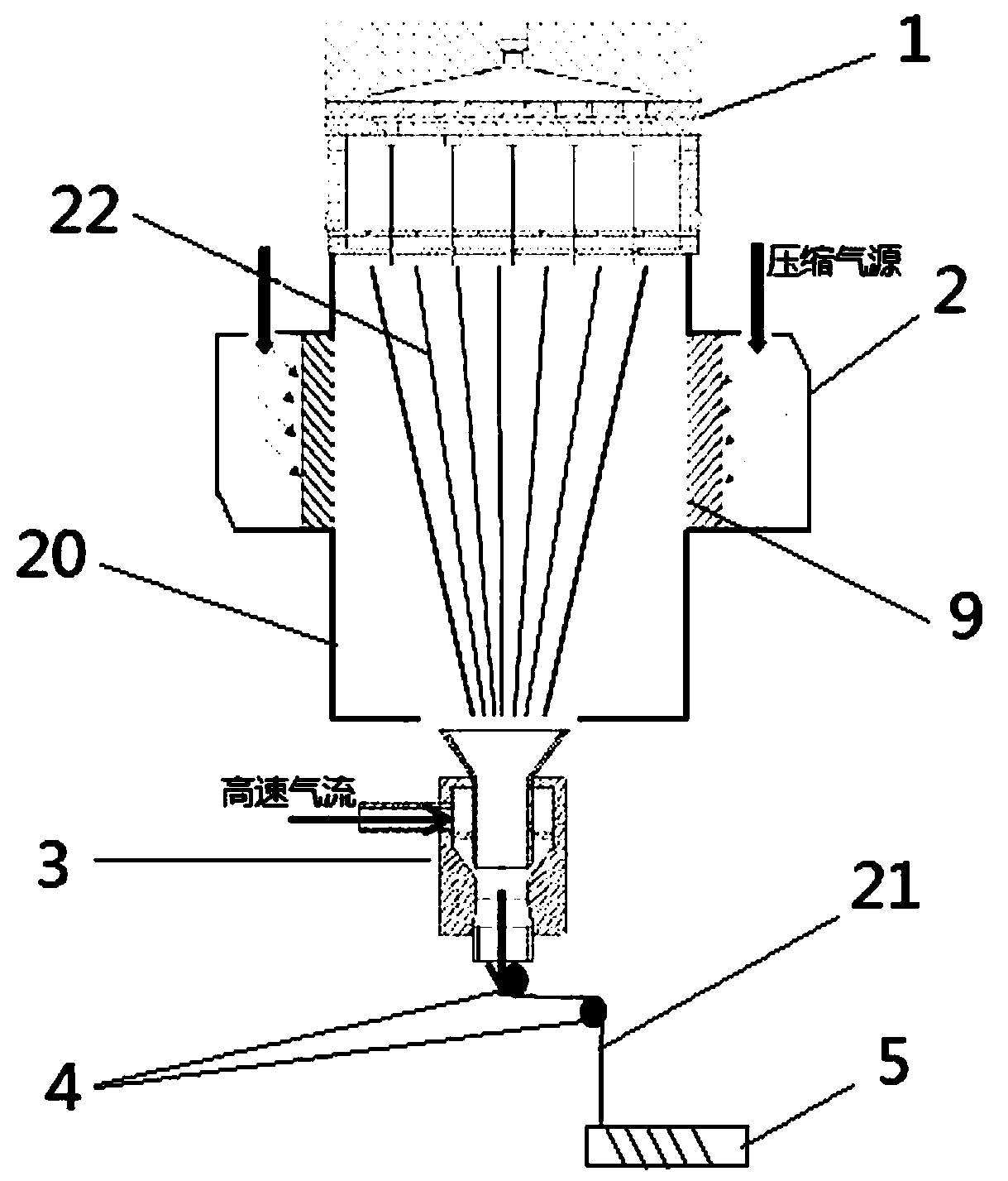
[0031] Step 1: adding a spinning solution into the solution jet spinning die, and the spinning solution is stretched, thinned, and solvent volatilized under the action of the solution jet spinning die to form scattered nanofibers;

[0032] Step 2: Connect the air inlet of the auxiliary air injection device to a compressed air source, and eject an obliquely downward airflow from the air injection pipe, and the nanofibers are straightened and accelerated Twisting and gathering to form nanofiber yarn bundles;

[0033] Step 3: The nanofiber yarn bundle enters the Venturi tube receiving system through the funnel-shaped yarn guide tube, and passes through the yarn guide roller under the vacuum adsorption of the Venturi tube receiving system. The bobbins are wound and c...

Embodiment 1

[0038] Such as figure 1 As shown, the present embodiment provides a continuous preparation device for nanofiber yarn, including a solution jet spinning die head 1, an auxiliary air jet device 2, a Venturi tube receiving system 3, a guide roller 4 and a bobbin 5, and the solution jet The spinning die head 1 is used to spray and generate scattered nanofibers 22, and the Venturi tube receiving system 3, the guide roller 4 and the bobbin 5 are sequentially arranged below the solution jet spinning die head 1; where as Figure 4 As shown, the Venturi tube receiving system 3 includes an air drafting nozzle 6, a funnel-shaped yarn guide tube 7 and a high-speed air pipe 8. One side of the stretch nozzle 6, and one end of the high-speed air pipe 8 communicates with the inside of the air-flow drafting nozzle 6, and the other end of the high-speed air pipe 8 is used to connect the high-speed air source; The air inlet of device 2 is connected with a compressed air source, and the inner si...

Embodiment 2

[0052] This embodiment provides a continuous preparation method for nanofiber yarn, which is based on the continuous preparation device for nanofiber yarn described in Example 1. In this embodiment, the structure and working principle of the continuous preparation device for nanofiber yarn All are the same as those in Embodiment 1, and will not be repeated here. Described nanofiber yarn continuous preparation method specifically comprises the following steps:

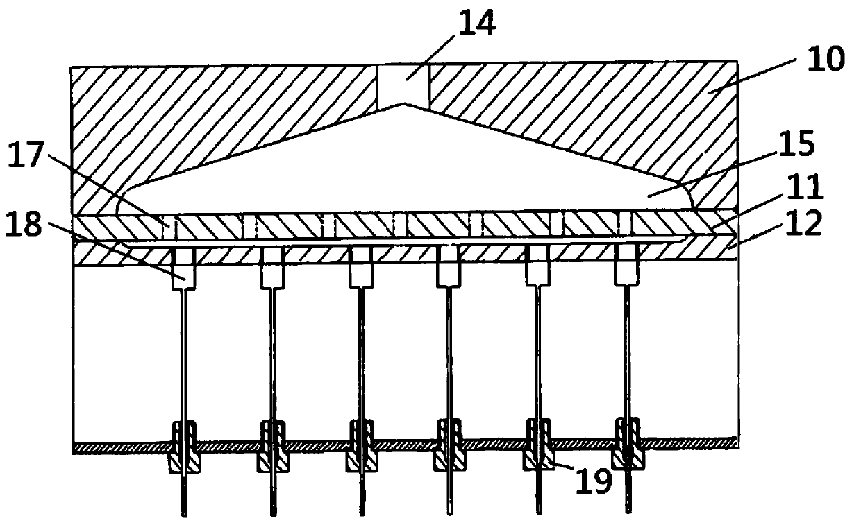
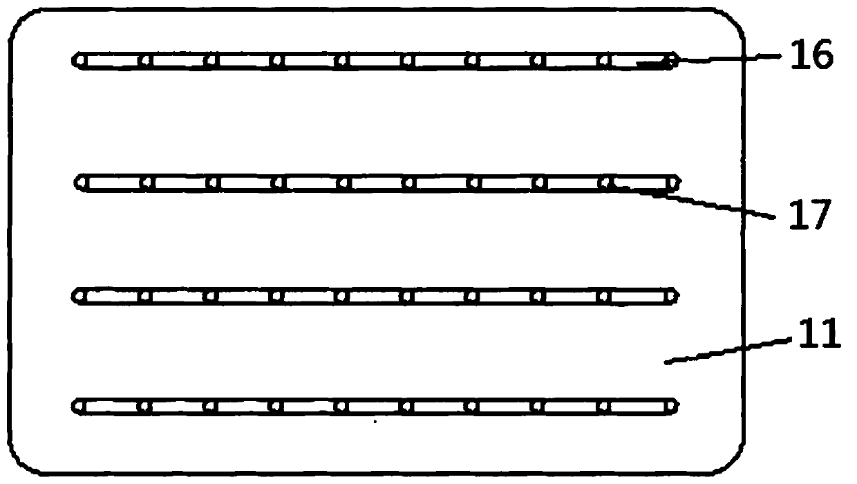
[0053] Step 1: Add spinning solution to the solution jet spinning die head 1, the spinning solution enters the feeding chamber 15 through the feeding hole 14 through the metering pump, and after distributing the horizontal guide groove on the distribution plate 11, the spinning solution is fed by The distribution holes 17 evenly enter each spinneret capillary 18, and the spinning solution is stretched, thinned, and solvent volatilized under the action of the solution jet spinning die to form nanofibers 22, which are sca...


PUM


Abstract

The invention discloses a continuous preparation device for nanofiber yarns. The continuous preparation device comprises a solution jet spinning die head, an auxiliary air jet device, a Venturi tube receiving system, a yarn guide roller and a spool. Spinning solution is subjected to drafting, thinning and solvent evaporation under the action of the spinning die head to obtain nanofibers, the auxiliary air jet device is additionally arranged to jet obliquely downward auxiliary airflow, the oriented nanofibers can be straightened, twisted and gathered under the action of side face to form nanofiber yarn tows, and the Venturi tube receiving system is matched with the yarn guide roller and the spool to timely collect generated yarns, so that the nanofiber yarns can be continuously produced. Besides, the invention further discloses a continuous preparation method for the nanofiber yarns. Operation is safe, simple and convenient, the problem of yarn length limitation is avoided, the generated yarns are good in orientation degree and mechanical property and can meet the high requirement of current nanofiber yarn preparation, and rapid development of nanofiber yarn application can be promoted.

Description

technical field [0001] The invention relates to the field of preparation of nanofiber yarns, in particular to a continuous preparation device and method for nanofiber yarns. Background technique [0002] Nanofiber yarn refers to a nanofiber assembly prepared by applying a certain twist to oriented nanofiber bundles with a certain aspect ratio. Nanofibers are processed into oriented nanofiber bundles or yarns, which have many excellent properties such as high crystallinity, good orientation, high tensile strength, and easy weaving. They are widely used in aerospace, microelectronics, photoelectric transmission, and biomedicine. It has been widely used in the field of nanofibers, and has shown great application potential compared with traditional nanofiber mats, and has developed into an important research hotspot in the field of nanofibers. [0003] During the preparation of nanofiber yarns, oriented nanofibers are the basis for constructing nanofiber yarns. At present, in ...

Claims


Application Information

Patent Timeline
Patent Type & Authority Applications(China)
IPC IPC(8): D01D5/04D01D5/14
CPCD01D5/04D01D5/14
Inventor 石磊庄旭品程博闻康卫民刘皓杨静静王瑾
Owner TIANJIN POLYTECHNIC UNIV
Learn More