A device and method for oil-water demulsification separation of heavy oil

A technology for oil-water separation and separation equipment, which is applied in the fields of hydrocarbon oil dehydration/demulsification, electrical/magnetic dehydration/demulsification, mechanical dehydration/demulsification, etc. It can improve the stability of crude oil, avoid secondary emulsification and improve separation efficiency.

Active Publication Date: 2021-05-18
新疆中亚石油天然气有限公司
View PDF5 Cites 0 Cited by
  • Summary
  • Abstract
  • Description
  • Claims
  • Application Information

AI Technical Summary

Problems solved by technology

Oil-water separation methods commonly used in oilfields, such as demulsification by adding demulsifiers, electrolysis, gravity sedimentation, etc., are difficult to achieve the ideal dehydration effect
In general heavy oil fields, the associated gas is limited and cannot be heated by burning natural gas, so other heating methods can only be adopted. At present, electric heating rods are generally used for heating, but the energy consumption is high and the heating efficiency is low (the heating efficiency is generally about 40%). Oil dehydration is an unsolved problem in oilfield development
[0003] The existing oil-water separation process flow is as follows: the oil-water emulsion passes through a primary separator, a secondary separator, electric heating or gas heating, electric stripping, and finally oil is produced. There are the following defects: (1) The traditional process is relatively complicated and takes up Large area and high labor intensity; (2) The separation process is mainly based on demulsification and sedimentation of demulsifiers. Water-soluble demulsifiers have a great impact on the quality of effluent water, and it is difficult for water discharge to meet environmental protection requirements.
Oil-soluble demulsifiers are highly volatile, toxic and harmful, and it is difficult to meet the requirements of environmental protection and the personal health of operating personnel; (3) Due to the lack of natural gas in the traditional process, electric heating rods must be used for heating. The conversion efficiency is generally about 40%, with high energy consumption and low efficiency; (4) Traditional separation process, the water content in the oil after separation is difficult to meet the online standard

Method used


Image

  • A device and method for oil-water demulsification separation of heavy oil
  • A device and method for oil-water demulsification separation of heavy oil
  • A device and method for oil-water demulsification separation of heavy oil

Examples


specific Embodiment 1

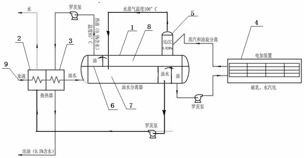
[0038] A heavy oil oil-water demulsification separation equipment, such as figure 1 As shown, it includes an oil-water separation tank 1, and also includes an electromagnetic induction heater 4 (such as Figure 11 shown) and a vapor-liquid cyclone separator 5 for effective separation of water vapor and liquid phase, the oil-water separation tank 1 is divided into a primary oil-water separation chamber 7 and a secondary oil-water separation chamber 8, a primary oil-water separation chamber 7 It is connected with the secondary oil-water separation chamber 8 through the electromagnetic induction heater 4 and the vapor-liquid cyclone separator 5 in sequence.

specific Embodiment 2

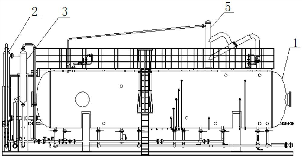
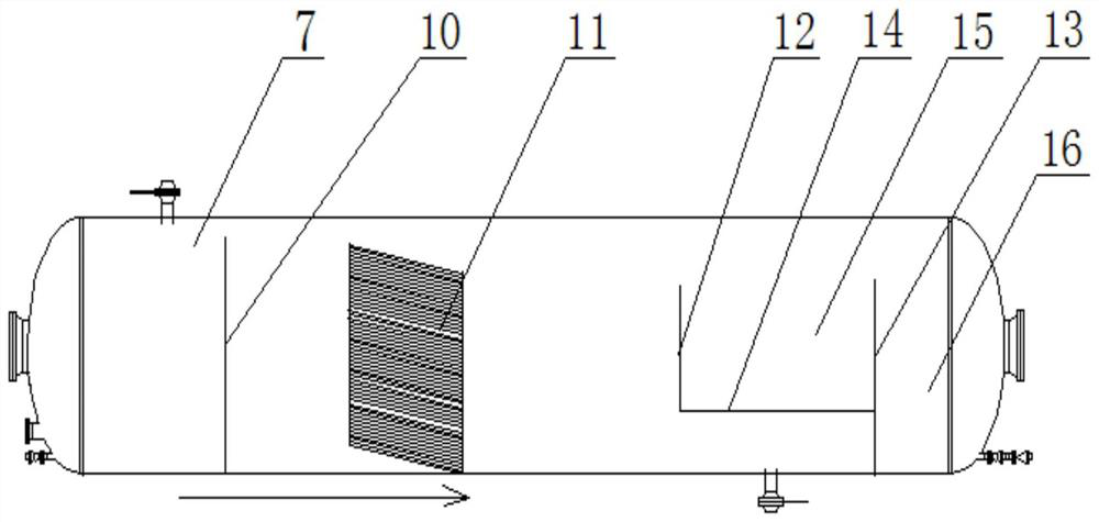
[0040] With above-mentioned specific embodiment 1, its difference is: as figure 2 As shown, the oil-water separation tank 1 is arranged horizontally, the primary oil-water separation chamber 7 and the secondary oil-water separation chamber 8 are separated by the longitudinal partition 6 along the axial direction of the oil-water separation tank 1, and the oil-water inlet ports of the primary oil-water separation chamber 7 are sequentially connected There is a second heat exchanger 3 and a first heat exchanger 2, the first heat exchanger 2 is provided with an incoming liquid inlet 9, and the water phase outlet of the primary oil-water separation chamber 7 is connected to the shell side of the first heat exchanger 2 The oil phase outlet of the primary oil-water separation chamber 7 is connected with the liquid inlet of the electromagnetic induction heater 4, and the liquid outlet of the electromagnetic induction heater 4 is connected with the feed inlet of the vapor-liquid cyclo...

specific Embodiment 3

[0045] A method for demulsifying and separating heavy oil from oil and water using a heavy oil and oil-water demulsification separation device according to the above specific embodiment, comprising the following steps:

[0046] The oil-water mixed liquid is sent to the first-stage oil-water separation chamber 7 of the oil-water separation tank 1 for oil-water separation, and the oil phase separated in the first-stage oil-water separation chamber 7 is sent to the electromagnetic induction heater 4 for processing, and the electromagnetic induction heater The heating temperature of 4 is controlled at 106°C, the electromagnetic field is controlled at 300A / M, the oil-water mixture treated by the intermediate frequency heater enters the vapor-liquid cyclone separator 5 at a constant temperature of 106°C, and the water vapor and liquid in the vapor-liquid cyclone separator 5 The cyclone rapid separation is formed, and the liquid mixture obtained after the cyclone separation enters the...


PUM

PropertyMeasurementUnit
conversion efficiencyaaaaaaaaaa

Abstract

The invention discloses a heavy oil oil-water demulsification separation equipment and method, comprising an oil-water separation tank, and is characterized in that it also includes an electromagnetic induction heater and a vapor-liquid cyclone separator. The oil-water separation tank is divided into a first-stage oil-water separation chamber and a second-stage oil-water separation chamber. The first-stage oil-water separation chamber is connected to the second-stage oil-water separation chamber through an electromagnetic induction heater and a vapor-liquid cyclone in turn. The separation method includes the following steps to mix the oil-water and send the liquid to the first-stage oil-water separation tank. The oil-water separation chamber is used for oil-water separation, and the oil phase separated in the first-stage oil-water separation chamber is sent to the electromagnetic induction heater for treatment. The liquid mixture obtained after flow separation enters the secondary oil-water separation chamber for oil-water separation again to obtain refined oil with a water content of less than 0.5%. The advantages are high oil-water separation efficiency, low energy consumption and high product purity.

Description

technical field [0001] The invention relates to an oil-water separator, in particular to a heavy oil oil-water demulsification separation device and method. Background technique [0002] my country is rich in heavy oil reserves, geological reserves account for about 17% of the total reserves, mainly distributed in Shengli, Liaohe, Xinjiang, Jilin, Dagang and North China oil fields. Most of the heavy oil produced in oil wells is oil-water emulsion. Since the specific gravity of heavy oil is close to that of water, the stability of the emulsion is strong. Oil-water separation methods commonly used in oilfields, such as demulsification by adding demulsifiers, electrolysis, and gravity sedimentation, are difficult to achieve the desired dehydration effect. In general heavy oil fields, the associated gas is limited and cannot be heated by burning natural gas, so other heating methods can only be adopted. At present, electric heating rods are generally used for heating, but the e...

Claims


Application Information

Patent Timeline
Patent Type & Authority Patents(China)
IPC IPC(8): C10G33/00C10G33/02C10G33/06
CPCC10G33/00C10G33/02C10G33/06C10G2300/1033
Inventor 李斌王建荣张广帅杨海军
Owner 新疆中亚石油天然气有限公司
Why Eureka
Try Eureka