High and low temperature combined cycle engine

A combined cycle, high and low temperature technology, used in combined engines, engine components, combustion engines, etc., can solve problems such as inability to stop, low efficiency, and exhaust gas pollution to the environment, and achieve full combustion, single combustion components, and improved engine efficiency. Effect

Active Publication Date: 2020-01-03
施爱龙
View PDF8 Cites 0 Cited by
  • Summary
  • Abstract
  • Description
  • Claims
  • Application Information

AI Technical Summary

Problems solved by technology

[0007] The purpose of the present invention is to provide high and low temperature combined cycle engine, to solve the need for additional starting equipment proposed in the above-mentioned background technology, can not stop during operation, otherwise will restart; efficiency is low and a large amount of waste gas pollutes the environment after fuel combustion The problem

Method used


Image

  • High and low temperature combined cycle engine
  • High and low temperature combined cycle engine
  • High and low temperature combined cycle engine

Examples


Embodiment 1

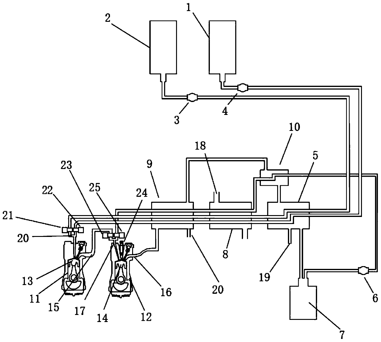
[0032] Embodiment one, see appendix figure 1 , LNG is stored in the fuel tank 1, and liquid oxygen is stored in the oxidizer tank 2. When the engine is working, the first cryopump 3 and the second cryopump 4 are started, and LNG and liquid oxygen are pumped into the first heat exchanger 5 to exchange heat with carbon dioxide gas, where the carbon dioxide gas is condensed into liquid and stored in liquid carbon dioxide Inside tank 7. LNG and liquid oxygen continue to enter the second heat exchanger 8, exchange heat with the air, absorb the heat in the air, cool the air, and at the same time become gaseous natural gas and gaseous oxygen or gas-liquid mixture, enter the third heat exchange Device 9. In the third heat exchanger 9, the natural gas, oxygen and the high-temperature exhaust gas discharged from the second exhaust port 16 perform heat exchange, the temperature of the high-temperature gas decreases, and part of the condensed water is discharged, and the remaining carbo...

Embodiment 2

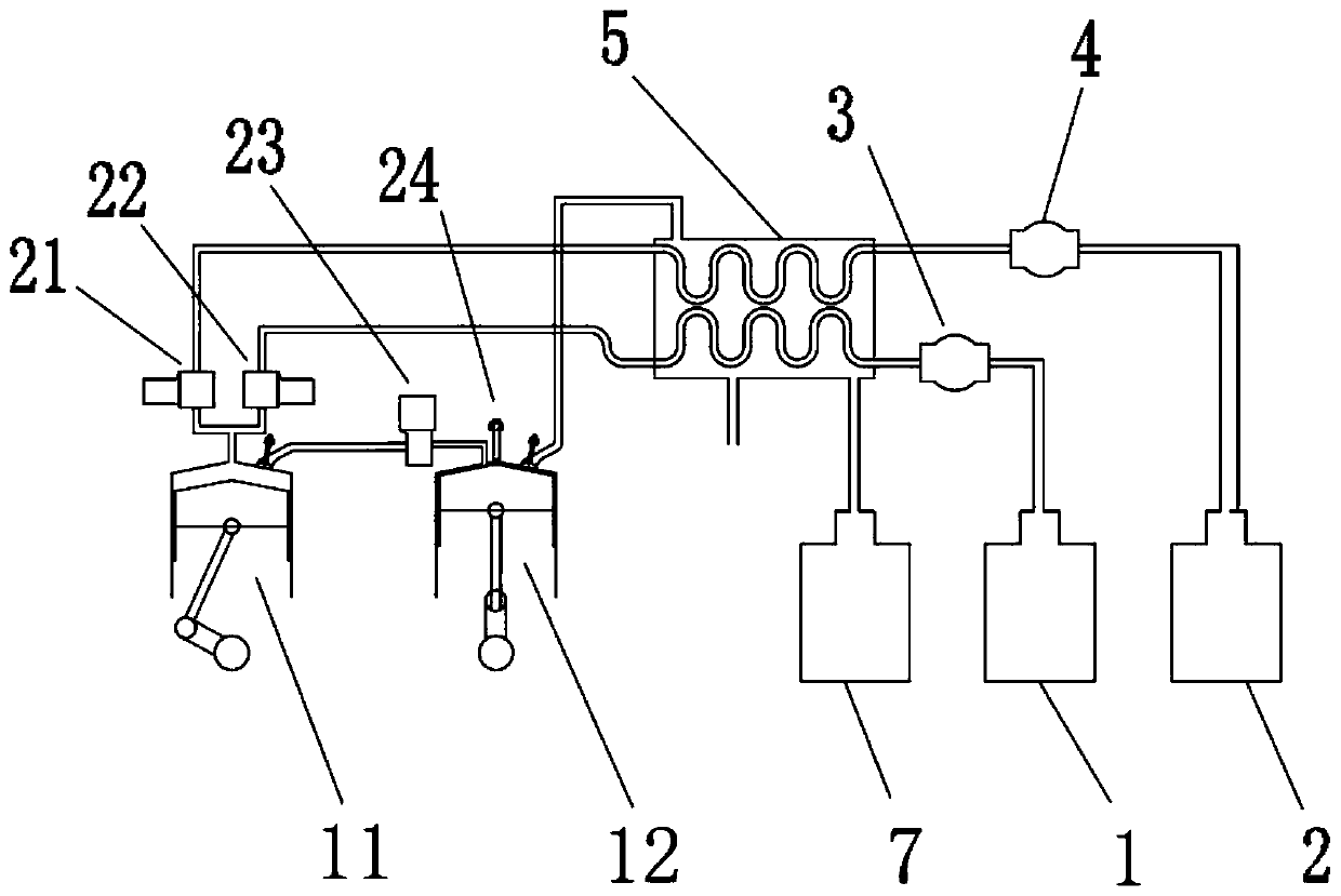
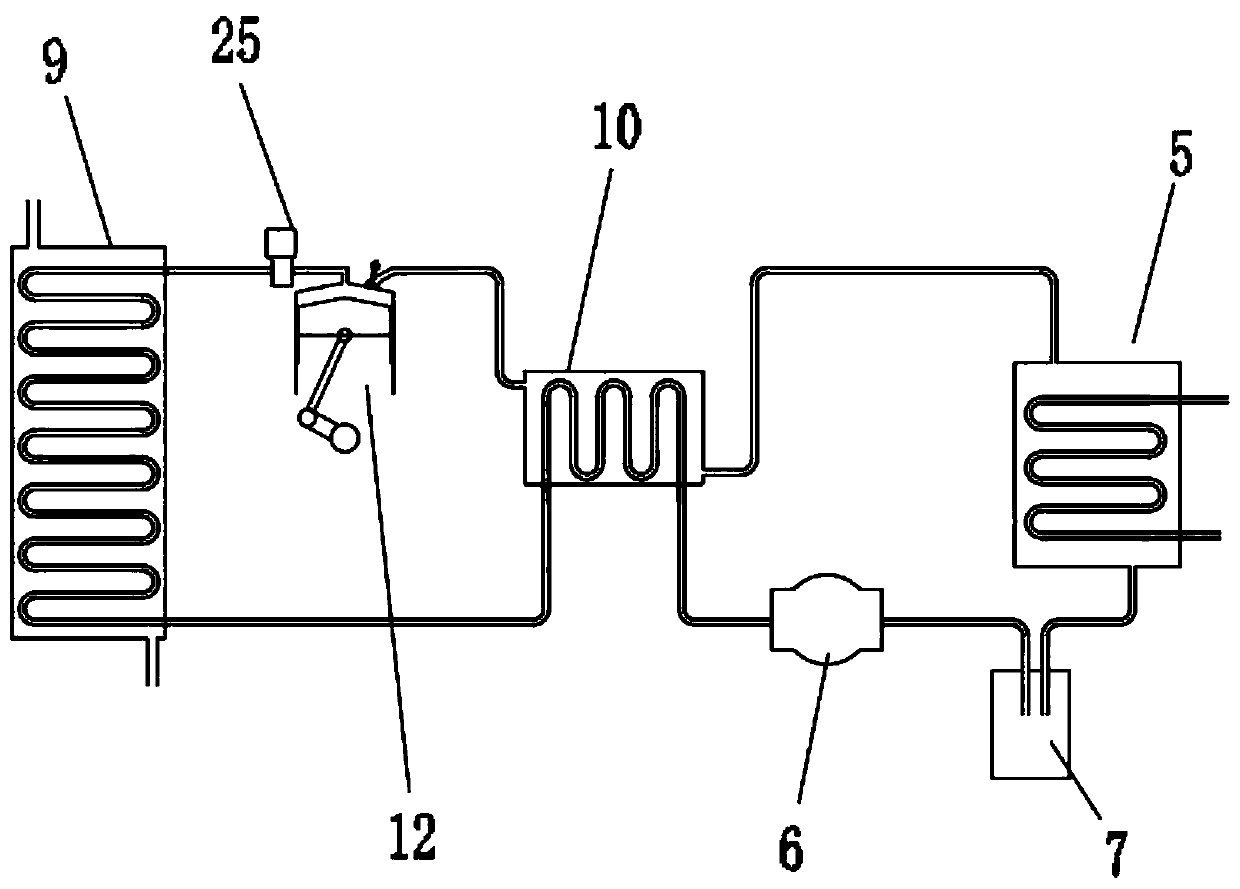
[0034] Embodiment two, such as figure 1 The invention shown here can be disassembled into figure 2 and image 3 two parts. figure 2 It consists of half a Rankine cycle and a half Otto cycle. image 3 is a complete Rankine cycle. image 3 The loop can recurse multiple times. figure 2 , image 3 They can be combined into one system, or they can form separate systems.

[0035] image 3 The Rankine cycle uses carbon dioxide as the working medium because carbon dioxide has a moderate boiling point, is easy to obtain, and is safe. The condensing agent can use liquid oxygen, LNG, liquid nitrogen and other gases with lower boiling points.

[0036] Combining Embodiment 1 and Embodiment 2, the present invention uses pure oxygen for combustion, which not only improves the combustion temperature and combustion speed, but also improves the combustion efficiency, that is, the efficiency of the engine is improved. At the same time, it reduces the emission of harmful gases such as...


PUM


Abstract

The invention discloses a high and low temperature combined cycle engine comprising a fuel tank, an oxidant tank, a first heat exchanger, a liquid carbon dioxide tank, a second heat exchanger, a thirdheat exchanger, a first cylinder and a second cylinder. A first piston is installed in the first cylinder. A second piston and a sparking plug are installed in the second cylinder. A gas inlet is fixedly connected to the top end of the first cylinder. A second gas inlet is fixedly connected to the top end of the second cylinder. A second cryogenic pump and a first cryogenic pump are connected tothe output ends of the fuel tank and the oxidant tank correspondingly. According to the high and low temperature combined cycle engine, liquid oxygen is adopted as an oxidant to replace air, burning components are simple, burning is more sufficient, zero emission can be achieved, the high and low temperature combined cycle engine can work in an environment without air, higher pressure and temperature are generated after burning, and engine efficiency is improved. Meanwhile, emission of nitrogen oxide, carbon monoxide and other harmful gases is reduced.

Description

technical field [0001] The invention relates to the technical field of engines, in particular to high and low temperature combined cycle engines. Background technique [0002] As an emerging energy source, LNG is mainly composed of methane. LNG is colorless, odorless, non-toxic and non-corrosive. Its volume is about 1 / 650 of the same volume of gaseous natural gas. The weight of LNG is only about 45% of the same volume of water. LNG is carried on the car as fuel The weight is also light, so it has been used in many automobile engines, but there is no engine specifically for LNG, and a four-stroke engine is used, using air as the oxidizer. Since most of the nitrogen is contained in the air, a large amount of heat will be taken away during combustion, and harmful gases such as nitrogen oxides and carbon monoxide will be generated. Moreover, the energy contained in the high-pressure gas generated after LNG gasification is not utilized and wasted in vain, and the four-stroke en...

Claims


Application Information

Patent Timeline
IPC IPC(8): F01B21/02F01B29/10F01B31/08F02B43/10F02B23/08F02G5/02F01K27/00F01K25/10
CPCF01B21/02F01B29/10F01B31/08F01K25/103F01K27/00F02B23/08F02B43/10F02B2043/103F02G5/02Y02T10/12Y02T10/30
Inventor 施爱龙
Owner 施爱龙
Why Eureka
Try Eureka