
Magnetic refrigeration heat exchanger and refrigeration heating system and method

A heat exchanger and magnetic refrigeration technology, applied in refrigeration and liquefaction, refrigerators, refrigeration components, etc., can solve the problems of large heat capacity of magnetic refrigeration heat exchangers, loss of magnetic core heat or cooling capacity, and difficulty in ductility. The effect of improving heat exchange efficiency, improving reliability and versatility, and solving the loss of direct contact

Pending Publication Date: 2020-01-07
CHINA THREE GORGES CORPORATION
View PDF3 Cites 3 Cited by
  • Summary
  • Abstract
  • Description
  • Claims
  • Application Information

AI Technical Summary

Problems solved by technology

However, the ductility of gadolinium, especially composite materials, is difficult to match with that of copper. During the rolling process, there may be situations such as hollowness, magnetic core leakage, and insufficient strength of the tubes. Moreover, the heat exchanger involved in this patent is not described in detail. Layout, runner, exhaust and other issues are not involved
[0006] At this stage, the magnetic cores of magnetic refrigeration heat exchangers are mainly plate type, tube type and particle type. Generally, the overall porosity is in the range of 0.4~0.6. No matter which type will form microchannel heat transfer, especially the particle type Capillary action is most likely to occur during the filling process to increase the resistance of the heat exchanger
Moreover, there will be liquid storage problems in the heat exchange pipes of the heat exchanger, which will cause the loss of heat or cooling capacity of the magnetic core. As the magnetic refrigeration technology matures and the system scale gradually expands, the heat capacity in the magnetic refrigeration heat exchanger will increase. to a non-negligible extent

Method used


Image

  • Magnetic refrigeration heat exchanger and refrigeration heating system and method
  • Magnetic refrigeration heat exchanger and refrigeration heating system and method
  • Magnetic refrigeration heat exchanger and refrigeration heating system and method

Examples


Embodiment 1

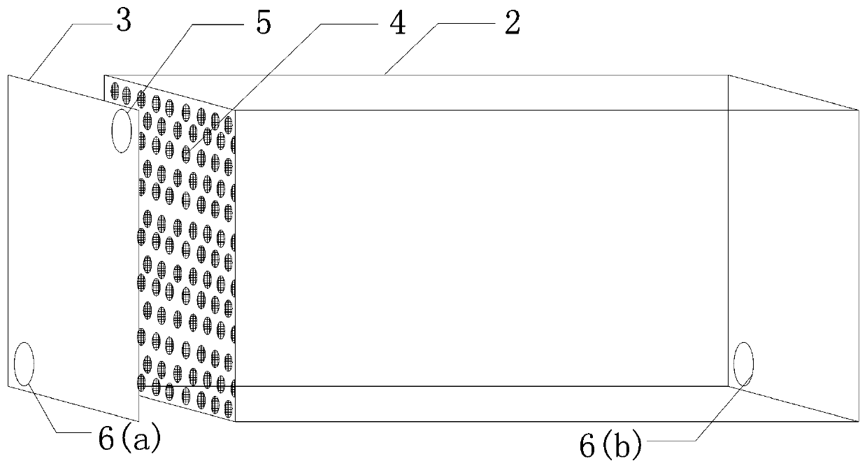
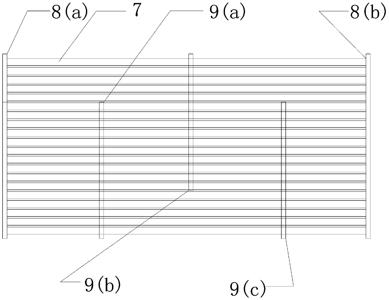
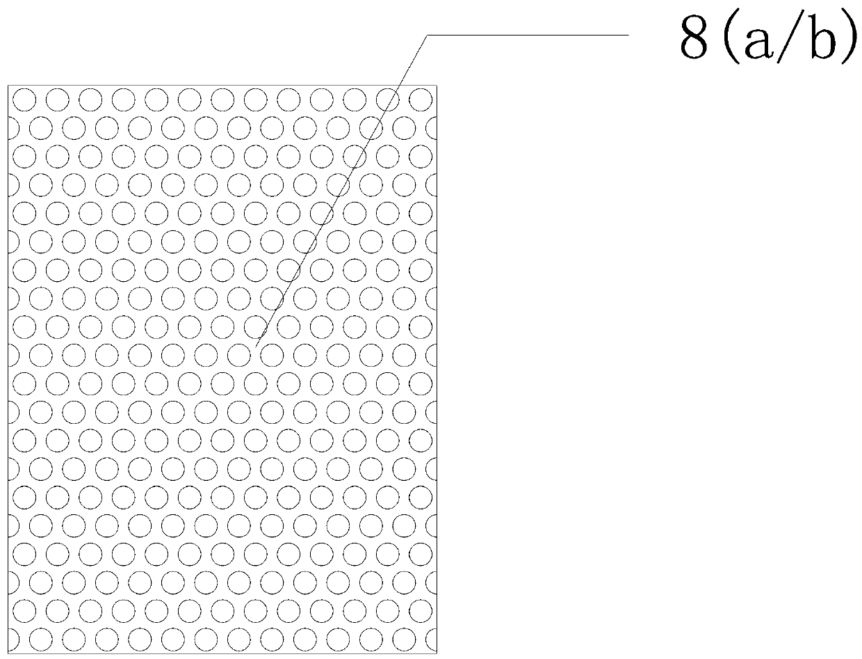
[0051] see Figure 1-10 , a magnetic refrigeration heat exchanger, which includes a rectangular heat exchanger 1, the rectangular heat exchanger 1 includes a heat exchanger shell 2, the inside of the heat exchanger shell 2 is installed with a magnetic working medium 12 The capillary matrix 4 is equipped with a cover plate 3 at both ends of the heat exchanger shell 2 and the capillary matrix 4 is packaged inside it; the upper edge of the cover plate 3 on both sides or the upper heat exchanger shell 2 The first through hole 5 for air intake and exhaust is processed in different processes in the interior; the second through hole 6 for circulating heat and cold fluid is processed on the lower edge of the cover plate 3 on both sides or the upper heat exchanger shell 2 (a) and the third through hole 6 (b). By adopting the magnetic refrigeration heat exchanger with the above structure, it adopts the magnetic refrigeration cycle to realize cyclic refrigeration or heating. It uses the...

Embodiment 2

[0061] according to figure 1 , the rectangular heat exchanger 1 is 40mm wide along the moving direction of the magnetic field, 30mm high along the magnetic field height direction, and 80mm long. . The shell and cover of the heat exchanger are cut or welded from 3mm aluminum alloy. The junction of the heat exchanger shell 2 and the cover plate 3 is welded with a 5mm boss for loading the silicone sealing strip and fixing the cover plate. According to the different processes in the heat exchanger, taking the four processes as an example, open a 5mm first through hole 5 on the cover plate or shell of the heat exchanger to connect the gas path through flanges or welded pipes; the cover plate of the heat exchanger Or open two 5mm second through holes 6 (a) and third through holes 6 (b) on the lower edge of the housing to connect the liquid circuit through flanges or welded pipes. The outer wall of the heat exchanger is affixed with a vacuum insulation board to insulate the heat e...

Embodiment 3

[0065] The refrigeration and heating system constructed by the above-mentioned magnetic refrigeration heat exchanger includes a rectangular heat exchanger 1 and a data acquisition and control system 17; the rectangular heat exchanger 1 cooperates with a movable magnetic field 13 arranged on its periphery, so that A heat storage container 14 and a cold storage container 15 are connected in parallel between the second through hole 6 (a) and the third through hole 6 (b) of the rectangular heat exchanger 1, and the outlet of the heat storage container 14 is connected to the heat storage The inlet of the side water pump 21 (a) is connected, and the outlet of the heat storage side water pump 21 (a) is connected to one inlet of the first electric three-way valve 18 (c); the other of the first electric three-way valve 18 (c) The inlet is connected to the outlet of the cold storage side water pump 21 (b), and the inlet of the cold storage side water pump 21 (b) is connected to the outle...


PUM


Abstract

The invention discloses a magnetic refrigeration heat exchanger and a refrigeration heating system and method. The magnetic refrigeration heat exchanger comprises a rectangular heat exchanger, whereinthe rectangular heat exchanger comprises a heat exchanger shell, a capillary matrix filled with a magnetic working medium is mounted in the heat exchanger shell, and cover plates are mounted at the two ends of the heat exchanger shell and encapsulates the capillary matrix inside the heat exchanger shell; the upper edges of the two side cover plates or the upper heat exchanger shell are processedwith a first through hole for air inlet and exhaust according to different processes in the heat exchanger; the lower edge of the two side cover plates or the upper heat exchanger shell is provided with a second through hole and a third through hole for circulating heat carrying and cooling fluid. The magnetic refrigeration heat exchanger aims at improving the reliability and universality of the heat exchanger and enhancing the heat exchange efficiency.

Description

technical field [0001] The invention relates to the field of magnetic refrigeration devices, in particular to a magnetic refrigeration heat exchanger, a refrigeration and heating system and method integrating packaging and enhanced heat transfer. Background technique [0002] Refrigeration technology accompanies all aspects of human production and life, and traditional gas compression refrigeration technology is currently the most mature and widely used refrigeration technology. In recent years, countries around the world have gradually reached a consensus on issues such as controlling greenhouse gas emissions and the destruction of the ozone layer. According to the Montreal Agreement, each signatory needs to gradually replace and phase out fluorine-containing working fluids. However, it is still difficult to balance the environmental protection, safety issues and cycle efficiency of new working fluids at this stage. As a new type of refrigeration technology, magnetic refr...

Claims


Application Information

Patent Timeline
Patent Type & Authority Applications(China)
IPC IPC(8): F25B21/00F25B39/00
CPCF25B21/00F25B39/00F25B2321/002Y02B30/00
Inventor 蔺新星尹立坤汤鹏
Owner CHINA THREE GORGES CORPORATION
Learn More