Probe disinfecting tank for ultrasonography department

A technology of disinfection box and ultrasound department, which is applied in the field of medical equipment, can solve the problems of operators endangering their own health, poor safety performance, and internal air circulation, etc., so as to avoid carrying germs, improve service life, and prevent cross-infection.

Pending Publication Date: 2020-01-14
THE SECOND PEOPLES HOSPITAL OF NANTONG
View PDF6 Cites 3 Cited by
  • Summary
  • Abstract
  • Description
  • Claims
  • Application Information

AI Technical Summary

Problems solved by technology

[0006] 1) When it is used, the probe is placed in the rubber pad in the fixed groove. Since the probe is placed in the rubber pad in the fixed groove, the bottom of the probe cannot shine on the disinfection lamp. Therefore, the probe cannot be used Thoroughly disinfect and clean, so that the probe still carries germs, and the hidden danger of cross-infection cannot be completely eliminated;
[0007] 2) Through the heating of the heating plate and the rotation of the fan blades in the fan box, the temperature generated by the heating plate can be quickly diffused, so that the temperature of the box can rise rapidly. At the same time, it can be used together with the disinfection lamp to improve the disinfection efficiency of the probe, although The disinfection efficiency of the probe is improved, but at the same time, the high temperature seriously affects the service life of the disinfection lamp and the probe;
[0008] 3) Since the inside of the probe is in a closed state when the probe is sterilized, the air inside does not circulate. At the same time, the oxygen in the air will form ozone under the action of ultraviolet rays. However, ozone is a poisonous gas. Take it out of the box When using the probe, the operator can easily endanger their own health by inhaling ozone;
[0010] 5) When the movable door is opened, the disinfection lamp can still work, and the ultraviolet rays generated by the disinfection lamp will cause damage to human eyes and skin, thus resulting in poor safety performance

Method used


Image

  • Probe disinfecting tank for ultrasonography department
  • Probe disinfecting tank for ultrasonography department
  • Probe disinfecting tank for ultrasonography department

Examples


Embodiment 1

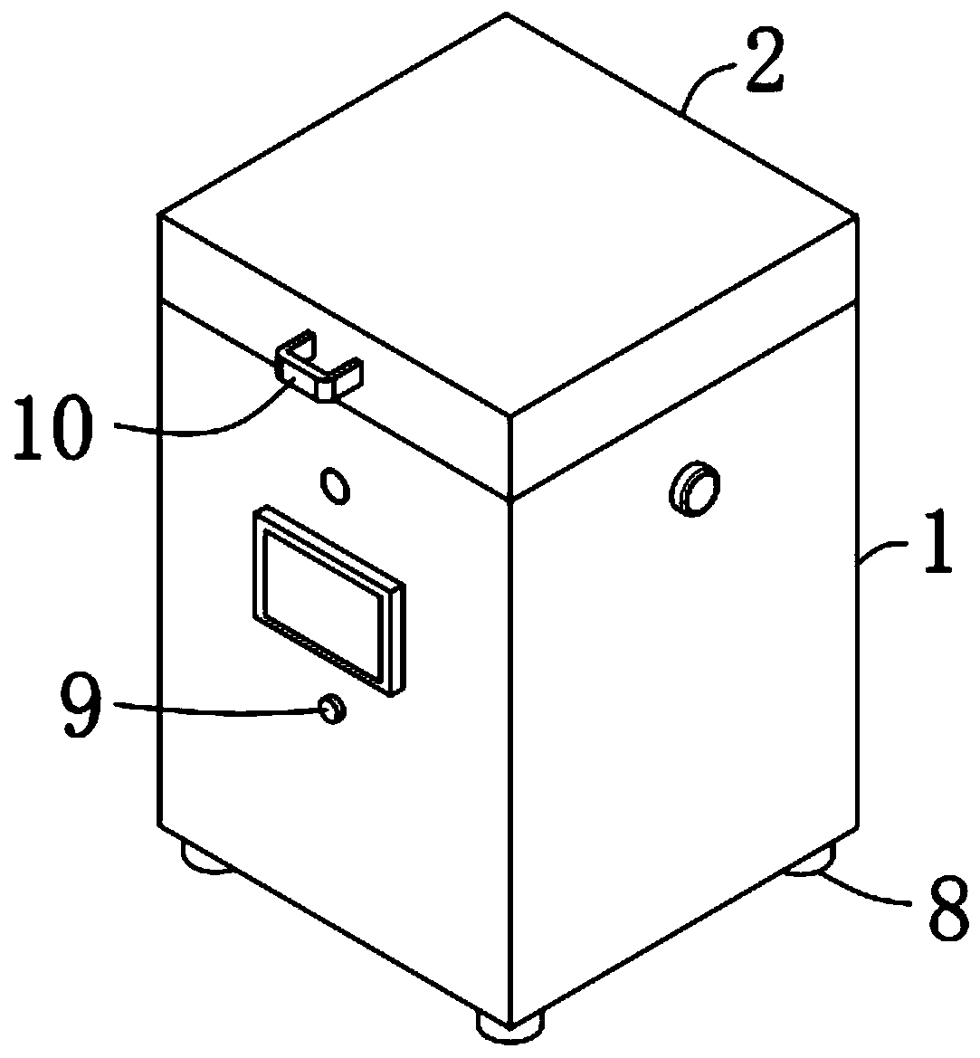
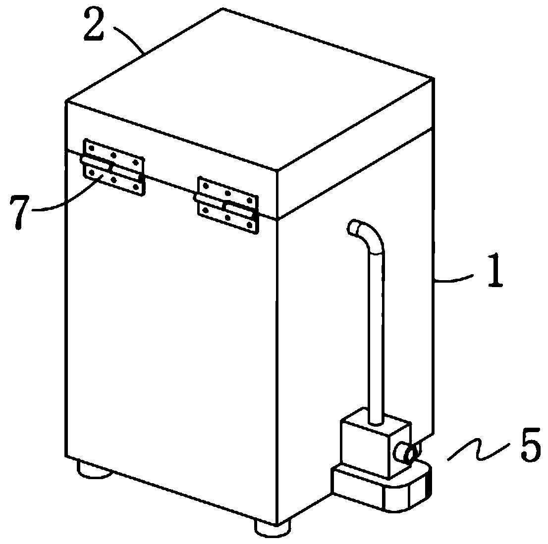
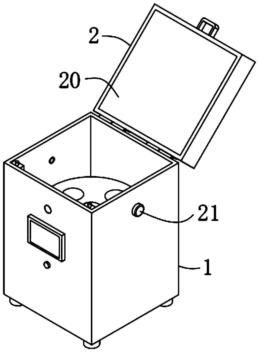
[0064] A kind of ultrasound probe disinfection box, such as Figure 1-2 As shown in and 4-6, an ultrasonic probe disinfection box includes a box body 1, a box cover 2, a rotary probe placement table 3, several groups of ultraviolet light generating units 4, accelerated air circulation units 5 and visual observation units 6, The upper part of the box body 1 is an open structure, the box cover 2 is hinged on the upper part of the box body 1 through a hinge 7, and the rotary probe placement platform 3 is fixedly installed on the inner bottom of the box body 1, Several groups of ultraviolet generating units 4 are fixedly installed inside the box cover 2, and several groups of ultraviolet generating units 4 are equidistantly arranged, and the accelerated air circulation unit 5 is fixedly installed on both sides of the box body 1. On the side wall, the visual observation unit 6 is fixedly installed at the front of the box body 1 .

[0065] By adopting the above-mentioned technical ...

Embodiment 2

[0089] The difference from Example 1 is that a protective layer is also provided on the surface of the rubber sheet 15, and the protective layer is prepared by the following method:

[0090] Take the following raw materials and weigh them by weight: 25 parts of epoxy resin, 15 parts of fluororesin, 10 parts of nano-silver powder, 8 parts of quartz powder, 14 parts of polyurethane, 15 parts of acrylic emulsion, 3 parts of paraffin, 2 parts of alcohol ester twelve, 2 parts of triethanolamine, 2 parts of emulsified silicone oil and 30 parts of water;

[0091] S1. Add the weighed acrylic emulsion, paraffin wax, alcohol ester dodeca, triethanolamine, emulsified silicone oil and water into the mixer and stir for 20min at a stirring speed of 500r / min to prepare a mixed solution;

[0092] S2, adding epoxy resin, fluororesin, nano-silver powder, quartz powder and polyurethane into a pulverizer for pulverization until the particle diameter of the material is not greater than 100nm, so a...

Embodiment 3

[0097] The difference with embodiment 2 is the preparation of protective layer, and its specific preparation method is as follows:

[0098] Take the following raw materials and weigh them by weight: 28 parts of epoxy resin, 18 parts of fluororesin, 11 parts of nano-silver powder, 9 parts of quartz powder, 16 parts of polyurethane, 18 parts of acrylic emulsion, 4 parts of paraffin, 3 parts of alcohol ester twelve, 3 parts of triethanolamine, 3 parts of emulsified silicone oil and 35 parts of water;

[0099] S1. Add the weighed acrylic emulsion, paraffin wax, alcohol ester dodeca, triethanolamine, emulsified silicone oil and water into the mixer and stir for 25min at a stirring speed of 550r / min to prepare a mixed solution;

[0100] S2, adding epoxy resin, fluororesin, nano-silver powder, quartz powder and polyurethane into a pulverizer for pulverization until the particle diameter of the material is not greater than 100nm, so as to obtain a mixed powder material;

[0101] S3. ...


PUM


Abstract

The invention discloses a probe disinfecting tank for ultrasonography department. The probe disinfecting tank comprises a tank body, a tank cover, a rotating type probe placing platform, a plurality of groups of ultraviolet ray generating units, an air circulation accelerating unit and a visual observing unit, wherein the upper part of the tank body adopts an opening structure; and the tank coveris hinged to the upper part of the tank body through hinges. Through the adoption of the probe disinfecting tank disclosed by the invention, probes can be guaranteed to be thoroughly disinfected, thesituation that the probes carry viruses is avoided, the hidden danger of cross infection is completely eliminated, the efficiency of disinfecting the probes can be improved, the problem that the service life of disinfecting lamps and the service life of the probes are severely influenced by high temperature is also solved, the generation of the phenomenon that when the tank is opened for taking the probes out, own health of the operators is easy to damage because of ozone intake, is avoided, eyes and skin of people are damaged by ultraviolet rays produced by the ultraviolet ray generating units in the process of observing the disinfecting situation in the tank body can be effectively prevented, the safety performance is good, and the purpose that when the tank cover is opened, a UV lamp pipe is automatically powered off can be realized.

Description

technical field [0001] The invention relates to the technical field of medical instruments, more specifically, it relates to a disinfection box for ultrasonic probes. Background technique [0002] The Department of Ultrasound is one of the medical departments of the hospital, which carries out ultrasound (two-dimensional ultrasound, Doppler ultrasound, interventional ultrasound, three-dimensional ultrasound, contrast-enhanced imaging) diagnosis and treatment. [0003] At present, ultrasonic examination is to observe the reflection of ultrasonic waves by the human body, generally called US ultrasonic examination, which uses weak ultrasonic waves to irradiate the body, and performs image processing on the reflected waves of tissues. Human body, by measuring the data and shape of the physiological or tissue structure, discovering the disease, and making a diagnosis method. During the B-ultrasound or color Doppler ultrasound examination, the B-ultrasound probe is used repeatedl...

Claims


Application Information

Patent Timeline
Patent Type & Authority Applications(China)
IPC IPC(8): A61L2/10A61L2/24A61L2/26C09D163/00C09D127/12C09D175/04C09D133/04C09D5/14C09D7/61
CPCA61L2/10A61L2/24A61L2/26A61L2202/12A61L2202/13A61L2202/14A61L2202/24C08K2003/0806C08K2201/011C08L2201/08C08L2205/035C09D5/14C09D7/61C09D163/00C08L27/12C08L75/04C08L33/04C08K13/02C08K3/08C08K3/36
Inventor 崔永芬葛建钢季玲颜艳
Owner THE SECOND PEOPLES HOSPITAL OF NANTONG
Why Eureka
Try Eureka