Reamer suitable for precision hole machining

A precision hole and reamer technology, applied in reamers, metal processing equipment, manufacturing tools, etc., can solve problems such as large chips, poor chip removal process, and affecting hole forming accuracy, so as to reduce power requirements and reduce roughness Degree value, the effect of brisk cutting process

Inactive Publication Date: 2020-01-14
SUZHOU AHNO PRECISION CUTTING TECH CO LTD
View PDF0 Cites 0 Cited by
  • Summary
  • Abstract
  • Description
  • Claims
  • Application Information

AI Technical Summary

Problems solved by technology

However, there are the following problems in the actual processing process: Generally speaking, the bottom surface of the bottom hole after the reaming drill still has a large amount to be cut, resulting in the bottom of the hole in the subsequent finishing process. Lots of chips
For the existing design milling cutter, the chip removal process is very poor, and it is easy to accumulate at the cutting end face, which increases the vibration of the reamer itself, deteriorates the processing conditions, and affects the hole forming accuracy
In addition, to a certain extent, the power demand for reaming machine tools is increased, thereby increasing the cost of equipment procurement and modification and upgrading

Method used


Image

  • Reamer suitable for precision hole machining
  • Reamer suitable for precision hole machining
  • Reamer suitable for precision hole machining

Examples


Embodiment Construction

[0021] In the description of the present invention, it should be understood that the orientation or positional relationship indicated by the terms "left", "right", etc. is based on the orientation or positional relationship shown in the drawings, and is only for the convenience of describing the present invention and simplifying the description. It is not intended to indicate or imply that the referred device or element must have a particular orientation, be constructed in a particular orientation, and operate in a particular orientation, and thus should not be construed as limiting the invention.

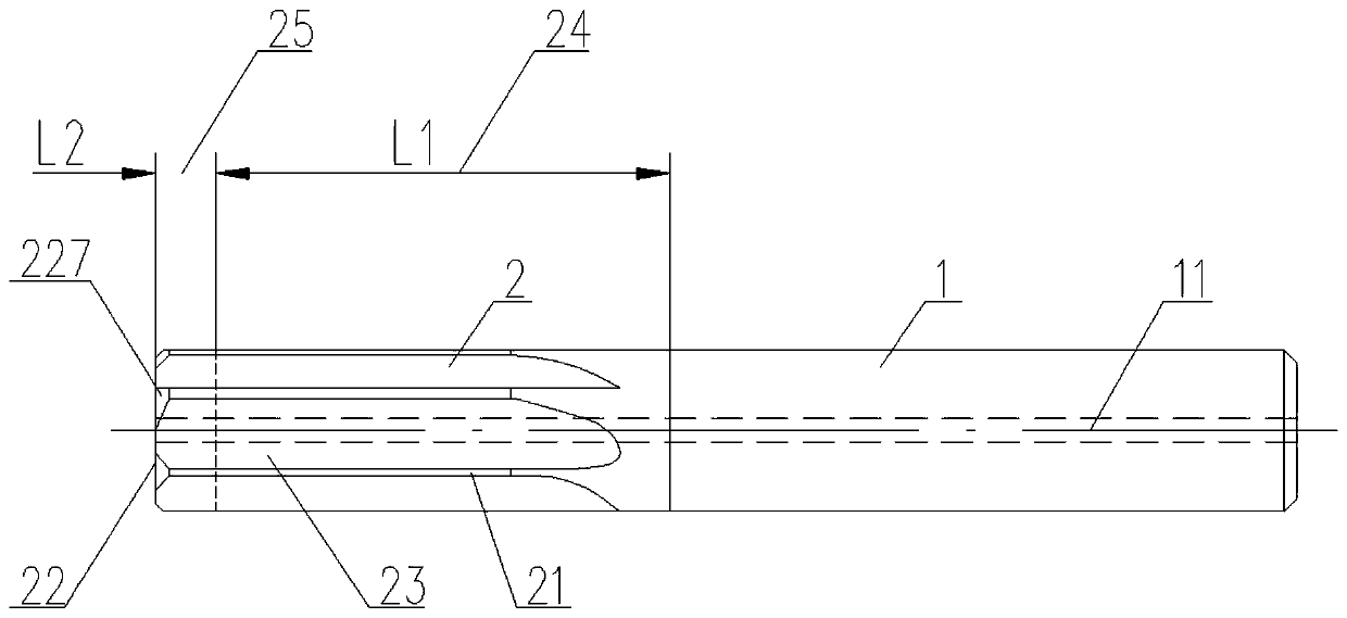
[0022] Below in conjunction with specific embodiment, content of the present invention is described in further detail, figure 1 It shows the front view of the first embodiment of the reamer suitable for precision hole machining in the present invention. It can be seen that it includes an integrally formed shank 1 and a cutting part 2, which are arranged sequentially from right to le...


PUM


Abstract

The invention relates to a reamer suitable for precision hole machining. The reamer comprises a handle part and a cutting part which are integrally formed, wherein the handle part and the cutting partare sequentially arranged in the direction from right to left, the cutting part comprises outer circular blades, end blades and chip removal grooves, the outer circular blades and the chip removal grooves both extend in a spiral line or a straight line around the outer side wall of the cutting part and are arranged alternately, the outer circular blades extend to the end surface of the cutting part to form the end blades, the at least one end blade is an avoiding tooth, namely, the at least one end blade is provided with a chamfered avoiding section which extends in the radial direction of the at least one end blade until extending to the peripheral side wall of the cutting part. In this way, chips are facilitated to be timely guided into the chip removal grooves and smoothly discharged,so that the situation that the chips are continuously accumulated on the cutting end surface is avoided, the vibration amount of the reamer itself is reduced, the roughness height of the hole wall ofa formed hole can be further effectively reduced, in addition, the contact surface of the reamer itself and the bottom surface of the bottom hole is effectively reduced, the cutting process is lighterand faster, and the requirement for the power of a reaming machine tool is reduced.

Description

technical field [0001] The invention relates to the technical field of cutting tool manufacturing, in particular to a reamer suitable for precision hole processing. Background technique [0002] Ductile iron has good comprehensive mechanical properties and low purchase cost, so it has a very wide range of applications, such as: auto parts, molds, valves and so on. The hole forming processing steps of conventional nodular cast iron are roughly as follows: 1) First, drill the bottom hole with the help of a twist drill; 2) Furthermore, use the reamer to enlarge the diameter of the bottom hole and improve its cylindricity and roughness; 3) Finally, finish machining with the help of a reamer to further improve the cylindricity and roughness of the reamed hole until it meets the detection standard. However, there are the following problems in the actual processing process: Generally speaking, the bottom surface of the bottom hole after the reaming drill still has a large amount t...

Claims


Application Information

Patent Timeline
IPC IPC(8): B23D77/00
CPCB23D77/00B23D2277/30
Inventor 余洪王弢颜晓龙
Owner SUZHOU AHNO PRECISION CUTTING TECH CO LTD
Why Eureka
Try Eureka