
Shale cluster well gas collection platform technological process and method

A process flow and cluster well technology, applied in the field of cluster well gas gathering platform testing and processing, can solve the problem of sand removal and metering accuracy failing to meet the standard requirements, safety, high efficiency, adverse effects of economical operation, and skid-mounted equipment and low degree of modularization, to achieve the effects of easy prying, intensive site layout, and good heat conduction effect

Inactive Publication Date: 2020-01-17
SOUTHWEST PETROLEUM UNIV
View PDF8 Cites 8 Cited by
  • Summary
  • Abstract
  • Description
  • Claims
  • Application Information

AI Technical Summary

Problems solved by technology

[0004] There are still many deficiencies in the current shale gas cluster well gas gathering platform production process, such as sand removal and metering accuracy not meeting the standard requirements, poor heating and separation efficiency, poor throttling control ability, equipment prying The low level of assembly and modularization, etc., lead to a greater safety risk in the production process of the gas gathering platform, and the economic benefits are not significant, and it will affect the follow-up gas gathering station and central processing station (including booster station, dehydration station, etc. Station) adverse effects on the safe, efficient and economical operation of the technological process

Method used


Image

  • Shale cluster well gas collection platform technological process and method
  • Shale cluster well gas collection platform technological process and method
  • Shale cluster well gas collection platform technological process and method

Examples


Embodiment Construction

[0021] The present invention will be further described below in conjunction with the accompanying drawings and specific embodiments.

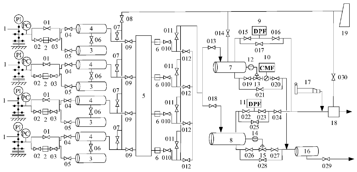
[0022] Such as figure 1 As shown, a shale gas cluster well gas gathering platform process is characterized in that it includes the following:

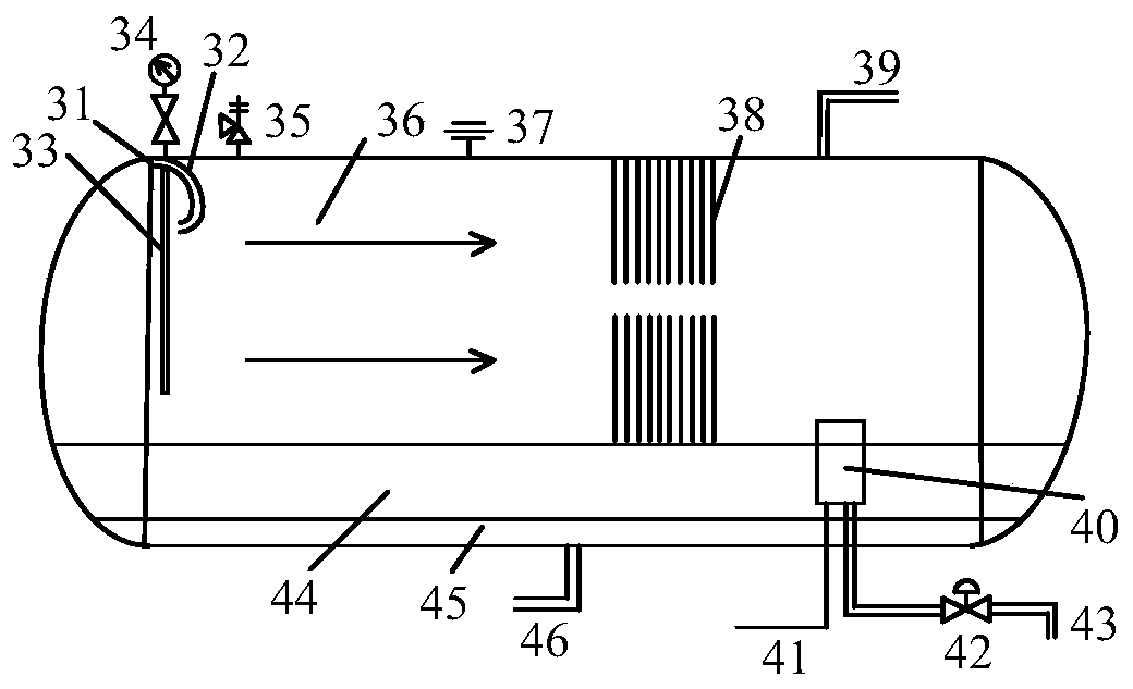
[0023] 1. During the liquid drainage production period, the liquid volume is large, the sand volume is high, the gas volume is small, and the pressure is high. Therefore, the process flow that can be adopted is: the gas-liquid-sand mixture coming out of the gas tree 1 first passes through the set near the wellhead. The electric throttle valve 2 is used for first-stage throttling; secondly, the cyclone desander 3 is used for centrifugal and sedimentation desanding; and then the filter desander 4 is used for filtration and separation again, so as to reduce the sand particles in the raw gas as much as possible content; and then heated through the 4-well type water jacket heating furnace 5 to prevent ice b...


PUM


Abstract

The invention relates to a cluster well gas collection platform technological process and method. The cluster well gas collection platform technological process and method meet the standard design requirement and specifically comprise the processes of wellhead throttling, sand removing and filtering, heating throttling, gas-liquid separation and alternate metering, pipe cleaning and ball serving,pre-pressurization and the like, namely, devices such as a cyclone desander, a filtering desander, an electric throttling valve, a water jacket heating furnace, a gas-liquid two-phase horizontal separator, a conical orifice plate flowmeter, a mass flowmeter, a pipe cleaner and ball serving barrel and a reciprocating piston compressor are included, skid-mounted integration and splicing mounting areadopted, carrying and dismounting are easy, and the cyclone desander and a production separator are structurally optimized. The technological processes and devices adopted in different production periods are different, in the liquid discharging production period, the two-stage sand removing, two-stage throttling and separation process with the large processing capacity is adopted, in the high-yield period and the stable-yield period, skid-mounted equipment with the surplus load can be dismounted and then carried to other newly-built platforms to be used, the platform construction and equipment mounting period is short, and the investment cost is low.

Description

technical field [0001] The invention belongs to the production technical field of a cluster well gas gathering platform for shale gas exploitation, and in particular relates to a process flow and method for testing and processing a cluster well gas gathering platform. Background technique [0002] Shale gas refers to an unconventional natural gas resource that is mainly accumulated in organic-rich dark mud shale and its interlayers, mainly in the form of adsorption or free. As a clean and efficient energy source, shale gas can be used for industrial fuel, chemical power generation and civil use, etc. It can fully alleviate the shortage of oil and gas resources at the present stage, increase the proportion of natural gas in the energy structure, solve the problem of energy shortage, and ensure my country's energy security , promote the development of green energy, and improve the ecological environment. According to relevant data, the geological resources of shale gas in my c...

Claims


Application Information

Patent Timeline
IPC IPC(8): E21B43/00E21B43/12E21B43/34E21B47/00E21B36/02E21B37/00
CPCE21B36/02E21B37/00E21B43/12E21B43/122E21B43/34E21B47/00
Inventor 彭浩廖柯熹何国玺冷吉辉李刚闪从新
Owner SOUTHWEST PETROLEUM UNIV
Learn More