Numerical control tooth grinding machine with slotting function

A gear grinding machine and function technology, which is applied in the direction of manufacturing tools, tool dressing of sawing machines, metal sawing equipment, etc. The effect of uniform size of sawtooth and additional cost saving

Inactive Publication Date: 2020-02-14
缙云县先锋工具有限公司
View PDF7 Cites 7 Cited by
  • Summary
  • Abstract
  • Description
  • Claims
  • Application Information

AI Technical Summary

Problems solved by technology

[0002] At present, the gear grinding machine is a machine tool that uses the grinding wheel as a grinding tool and saw blades and other tool tooth surfaces. It also has the function of eliminating the deformation after heat treatment and improving the accuracy of the saw blade. However, the current gear grinding machines have the following problems: Problems, 1. The grinding wheel used for grinding teeth has a large error when it is raised and lowered, and the size of the processed saw teeth is different; it affects the use. 2. After the processing is completed, the tooth bottom of the saw blade cannot be completely ground, which affects the strength; 3. When the saw blade needs to be grooved at the tooth top after processing, it has to be disassembled and installed on another tooth top groove mechanism, which not only reduces the processing accuracy, but also increases the processing cost and reduces the production efficiency; 4. The angle and position of the coolant injection cannot be adjusted during the gear grinding process, which is not convenient for cooling and heat dissipation, and the sprayed coolant cannot be effectively recycled; 5. The oil fume cannot be effectively collected and diluted during the gear grinding process, which is easy to cause blockage

Method used


Image

  • Numerical control tooth grinding machine with slotting function
  • Numerical control tooth grinding machine with slotting function
  • Numerical control tooth grinding machine with slotting function

Examples


Embodiment Construction

[0023] The present invention will be further described below in conjunction with accompanying drawing:

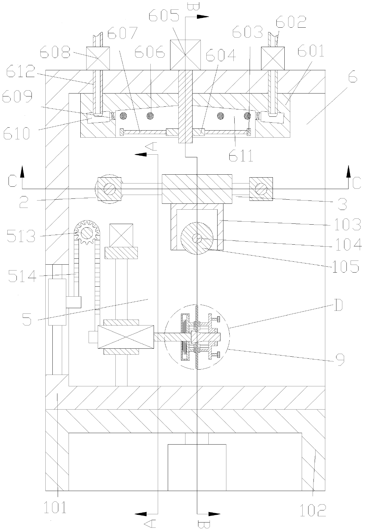
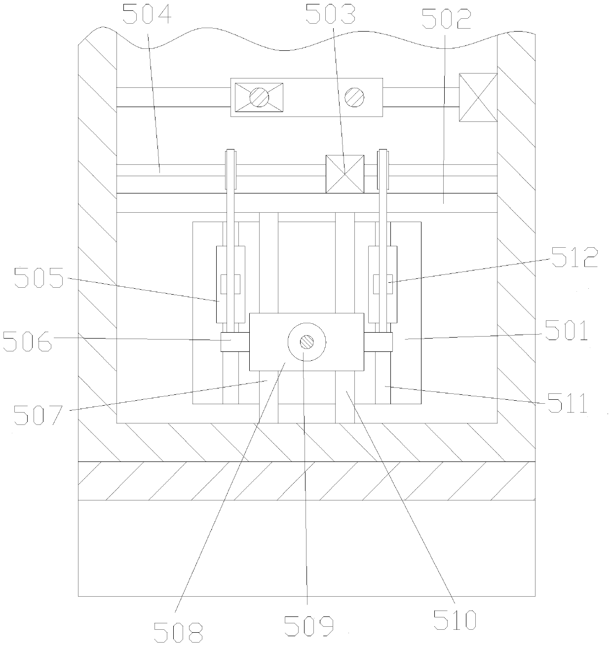
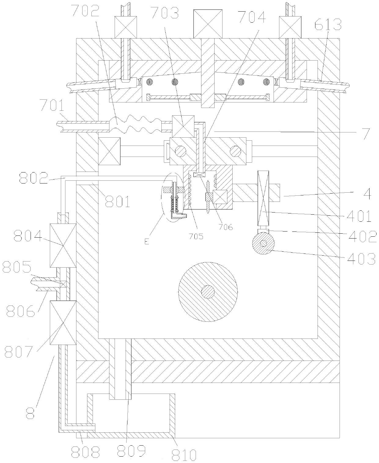
[0024] Refer to attached figure 1 , 2 , 3, 4, 5, 6, 7, 8: the CNC gear grinding machine with slotting function in this embodiment includes a box body 101, and a concave base 102 is fixedly installed on the bottom of the box body 101, and the Inside the box body 101, a traverse mechanism 2 is installed. A grinding wheel box 103 with a bottom connected to the outside is installed on the traverse mechanism 2. A first motor 104 is installed on the inner wall of the grindwheel box 103. The output shaft of the first motor 104 is A grinding wheel 105 whose bottom extends to the bottom of the grinding wheel box 103 is fixedly installed at the bottom of the box body 101. An elevating mechanism 5 cooperating with the grinding wheel 105 is installed inside the box body 101. A saw blade 905 is installed on the elevating mechanism 5. A slotting mechanism 4 for slotting saw blades is f...


PUM


Abstract

The invention discloses a numerical control tooth grinding machine with a slotting function. The numerical control tooth grinding machine comprises a box body, a concave base is fixedly installed at the bottom of the box body, a translation mechanism is installed inside the box body, and an abrasion wheel box of which the bottom is communicated with the outside is installed on the translation mechanism. The numerical control tooth grinding machine has the advantages of being simple in structure and easy to operate, saw webs can move up and down, thus errors generated in the traditional machining mode are reduced to guarantee the uniformity of the size of sawteeth, the tooth bottoms of the saw webs can be immediately slotted after tooth grinding on the saw webs is finished, extra detachmentis omitted, the working efficiency is improved, and the cost is reduced; the jetting angle and the jetting position of cooling liquid can be adjusted, and machining of the saw webs with different models can be better adapted to; and moreover, the cooling liquid can be recycled, extra cost is reduced, during machining, smoke can be quickly and timely absorbed and discharged after being diluted, subsequent treatment is facilitated, blockage on the device caused by the oil is also avoided, and the numerical control tooth grinding machine is simple, efficient, rapid and convenient.

Description

technical field [0001] The invention relates to the technical field of gear grinding machines, in particular to a numerically controlled gear grinding machine with a slotting function. Background technique [0002] At present, the gear grinding machine is a processing machine tool that uses the grinding wheel as a grinding tool and saw blade and other tool tooth surfaces. It also has the function of eliminating the deformation after heat treatment and improving the accuracy of the saw blade. However, the current gear grinding machine has the following problems: Problems, 1. The grinding wheel used for grinding teeth has a large error when it is raised and lowered, and the size of the processed saw teeth is different; it affects the use. 2. After the processing is completed, the tooth bottom of the saw blade cannot be completely ground, which affects the strength; 3. When the saw blade needs to be grooved at the tooth top after processing, it has to be disassembled and instal...

Claims


Application Information

Patent Timeline
Patent Type & Authority Applications(China)
IPC IPC(8): B23D63/14B23D63/20
CPCB23D63/14B23D63/20
Inventor 卢胜卢敏吴建乐
Owner 缙云县先锋工具有限公司
Why Eureka
Try Eureka