
Laser interference photoetching system

A laser interference lithography and beam technology, which is applied in the field of optical instruments and equipment, can solve problems such as difficulty in realizing large-area high-precision grating production

Active Publication Date: 2020-02-18
TSINGHUA UNIV +1
View PDF16 Cites 5 Cited by
  • Summary
  • Abstract
  • Description
  • Claims
  • Application Information

AI Technical Summary

Problems solved by technology

Suzhou Sudaweige Optoelectronics Technology Co., Ltd. discloses a parallel interference lithography system in the Chinese patent publication number CN101846890. The lithography system uses a grating to split light and a lens to combine light, but there is no interference pattern phase locking device in the interference lithography system. , so the laser interference lithography system is also difficult to realize the fabrication of large-area high-precision gratings

Method used


Image

  • Laser interference photoetching system
  • Laser interference photoetching system
  • Laser interference photoetching system

Examples


Embodiment Construction

[0035] In order to further illustrate the technical means and effects of the present invention for solving technical problems, the present invention will be further described in detail below in conjunction with the accompanying drawings and specific embodiments. It should be noted that the provided accompanying drawings are schematic and mutually exclusive They are not drawn to scale or scale, and therefore the drawings and specific examples are not intended to limit the scope of protection claimed by the invention.

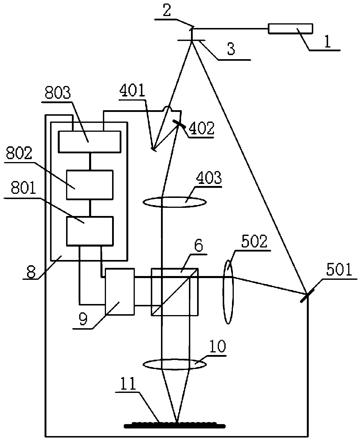
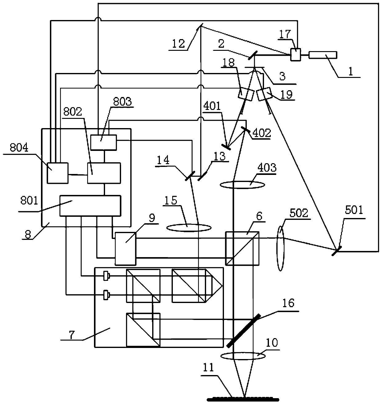
[0036] Such as figure 1 The optional embodiment of the laser interference lithography system shown includes a laser 1, a first mirror 2, a grating beam splitter 3, a second mirror 401, a first gimbal mirror 402, a first lens 403, a second Gimbal mirror 501, second lens 502, dichroic prism 6, control module 8, angle measurement module 9, third lens 10 and substrate 11; the control module 8 includes a signal processing terminal 801, a controller 802 and a driver 80...


PUM


Abstract

The invention belongs to the technical field of optical instruments and meters, and discloses a laser interference photoetching system, which comprises a laser, a first reflector, a grating beam splitter, a second reflector, a first universal reflector, a first lens, a second universal reflector, a second lens, a beam splitter prism, a control module, an angle measurement module, a third lens anda substrate, wherein the control module comprises a signal processing end, a controller and a driver; the signal processing end is connected with the angle measuring module; the controller is connected with the signal processing end and the driver; and the driver is connected with the first universal reflector and the second universal reflector. A light source emitted by the laser is divided intotwo beams of light through the system and focused on the substrate for exposure; and by adjusting the exposure angle, the manufacturing of the large-area grating with the gradient period is realized.The size of the grating manufactured in a scanning interference photoetching mode is not limited by the size of an exposure light spot, and a large-size gradient period grating can be manufactured.

Description

technical field [0001] The invention belongs to the technical field of optical instruments and meters, and in particular relates to a laser interference photolithography system, which can be used for the manufacture of large-scale gradually changing periodic gratings. Background technique [0002] Laser interference lithography is an important technology for manufacturing micro-nano array devices by exposing photosensitive substrates with periodic patterns generated by the interference of two or more laser beams. Array, dot matrix, microlens array and other devices, these microarray devices are widely used in national defense, people's livelihood, scientific research and other fields. [0003] Grating devices are key devices in major engineering systems such as large astronomical telescopes, inertial confinement fusion laser ignition systems, and photolithography systems. In recent years, the requirements for size, grid line density, and accuracy have been continuously impro...

Claims


Application Information

Patent Timeline
IPC IPC(8): G03F7/20
CPCG03F7/70408G03F7/704G03F7/7055G02B5/1857G03F7/2053
Inventor 王磊杰朱煜张鸣徐继涛李鑫成荣杨开明胡金春
Owner TSINGHUA UNIV
Learn More