
Intelligent crystal oscillator phase noise comprehensive compensation method

A comprehensive compensation and phase noise technology, applied in the electronic field, can solve problems such as large differences in adaptability, multi-system resource volume, weight and power consumption, frequency source vibration and noise reduction design confusion, etc., to achieve the effect of meeting the use requirements

Active Publication Date: 2020-02-18
SOUTHWEST CHINA RES INST OF ELECTRONICS EQUIP
View PDF8 Cites 2 Cited by
  • Summary
  • Abstract
  • Description
  • Claims
  • Application Information

AI Technical Summary

Problems solved by technology

However, in actual engineering, in order to meet the system requirements, developers often need to continuously improve the vibration isolation rate, which usually requires more system resources (volume, weight, power consumption, number of signal channels), so that high-purity The frequency source system can only stay at the laboratory level for a long time, and the environmental adaptability of the frequency source system of the same design scheme in the vibration environment is quite different, which brings great confusion to the vibration and noise reduction design of the frequency source

Method used


Image

  • Intelligent crystal oscillator phase noise comprehensive compensation method
  • Intelligent crystal oscillator phase noise comprehensive compensation method
  • Intelligent crystal oscillator phase noise comprehensive compensation method

Examples


Embodiment 2

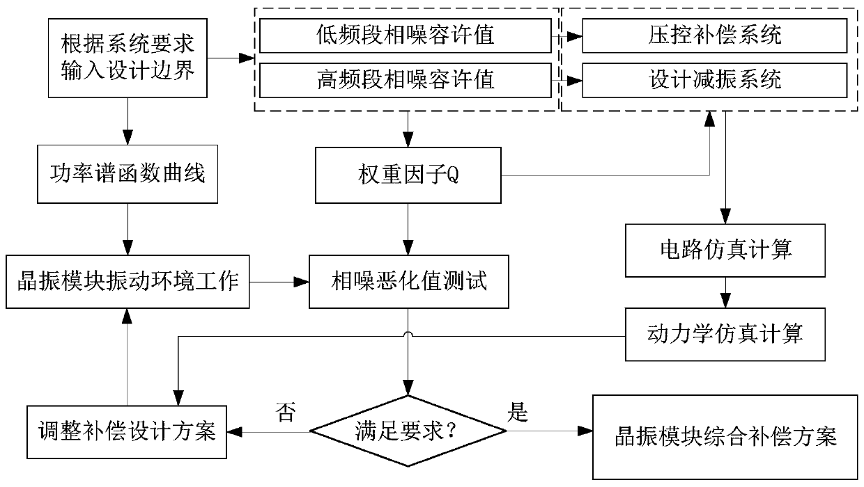
[0052] On the basis of Embodiment 1, step 5 is also included: selecting parameters of related devices according to the determined allowable value of phase noise, and simulating the phase noise compensation system to determine the compensation design scheme. The simulation includes circuit simulation and dynamics simulation, and the noise reduction effect is estimated by using circuit simulation software and dynamics simulation software to perform corresponding simulation calculations.

[0053] Wherein, the simulation specifically includes circuit simulation and dynamic simulation. After the technical boundary of the noise reduction system is determined, parameters such as acceleration sensors and pressure-sensitive shock absorbers are allowed to be selected. On this basis, the use of Circuit simulation software and dynamics simulation software perform corresponding simulation calculations to estimate the noise reduction effect.

[0054] Steps include:

[0055] Simulate the ph...

Embodiment 3

[0063] On the basis of Embodiment 2, after the design target and design scheme are determined, the actual use of the corresponding compensation principle prototype is usually different from the theoretical and simulation calculations. Therefore, it is necessary to design experiments that focus on key frequency points, focus on the simulation and experimental data of key frequency points, and record the difference value of key frequency points as ΔL v . And adjust the weight factor of the system design. Since the weight factor is one-dimensional, the design scheme that best meets the system requirements is obtained through conventional iteration and verified by experiments.

[0064] Wherein, the iterative method specifically includes: by testing in the working environment mentioned in step 2, the detection of the phase noise deterioration value is carried out, and the experimental verification whether the compensation design scheme meets the requirements of the phase noise of e...


PUM


Abstract

The invention provides an intelligent crystal oscillator phase noise comprehensive compensation method, which relates to the technical field of electronics. An electronic system in which a crystal oscillator is arranged is provided, and the method comprises the following steps: (1) determining a phase noise allowable value and a noise reduction frequency band according to the requirements of the electronic system; (2) acquiring a power spectrum function of an electronic system and an actual phase noise value of a crystal oscillator; (3) calculating a weight factor Q of the electronic system; and (4) designing a phase noise compensation system according to the weight factor and the phase noise allowable value, and by using the intelligent crystal oscillator phase noise comprehensive compensation method, the crystal oscillator module can keep high-stability frequency signal output in a severe vibration environment, and meanwhile, the module is prevented from being damaged under random vibration.

Description

technical field [0001] The invention relates to the field of electronic technology, in particular to an intelligent crystal oscillator phase noise comprehensive compensation method. Background technique [0002] The frequency source system is composed of a crystal oscillator module and a frequency synthesis circuit. Under vibration conditions, not only the working state of the crystal resonator in the crystal oscillator module is affected by vibration, but also circuit devices such as capacitors, inductors, and varactors will also cause phase noise deterioration of the oscillator. , the phase noise deterioration value of the entire frequency source system can reach 10dB-50dB. During the flight test, the measurement accuracy of the external measurement equipment often decreased, the signal had low-frequency interference modulation or the phase-locked loop lost lock, etc., which directly caused the system to fail to work normally. With the miniaturization of electronic equipm...

Claims


Application Information

Patent Timeline
IPC IPC(8): H03B5/04H03L7/00
CPCH03B5/04H03L7/00Y02T90/00
Inventor 冷国俊尹本浩保宏吴穹赖天华张文锋侯照临
Owner SOUTHWEST CHINA RES INST OF ELECTRONICS EQUIP
Learn More