
Device and method for removing oils in waste aluminum-based catalyst through continuous refluxing

A technology of spent catalysts and catalysts, applied in chemical instruments and methods, catalyst regeneration/reactivation, physical/chemical process catalysts, etc., can solve problems such as high equipment requirements, large alcohol degradation, complex processes, etc., to reduce operating costs, Strong adsorption, environmental friendly effect

Active Publication Date: 2020-02-21
KUNMING UNIV OF SCI & TECH
View PDF11 Cites 0 Cited by
  • Summary
  • Abstract
  • Description
  • Claims
  • Application Information

AI Technical Summary

Problems solved by technology

[0009] The above method of removing oil from the surface of the spent catalyst and removing "oily substances" has the following disadvantages: 1) the high energy consumption of the roasting method, the difficulty in controlling the treatment temperature, the generation of toxic and harmful gases, and the formation of multi-metal refractory composite oxides; 2) The washing method adds water-soluble polymer dispersant, alcohol and other substances, as well as ultrasonic vibration and mechanical stirring, which requires high equipment and complicated processes, and converts the problem into wastewater treatment, which does not solve the fundamental problem; 3) Patent CN 106902896A Although it does not cause waste of resources, it is difficult to separate the separated alcohol and oil, and the recovery of alcohol is complicated; the degradation of alcohol is large, and a large amount of supplement is required, and there is no fundamental solution to the complete separation of the oil from the waste aluminum-based catalyst and the valuable elements in the catalyst. question

Method used


Image

  • Device and method for removing oils in waste aluminum-based catalyst through continuous refluxing
  • Device and method for removing oils in waste aluminum-based catalyst through continuous refluxing

Examples


Embodiment 1

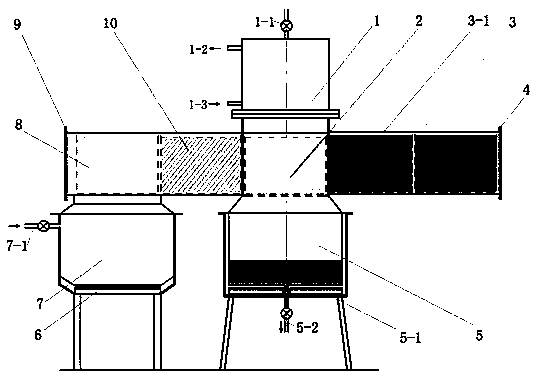
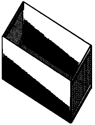
[0035] Embodiment 1: A kind of continuous reflux removes the device of oil in waste aluminum-based catalyst (see figure 1 ), including a horizontal spent catalyst deoiling treatment chamber and a screen frame 3 for containing spent catalyst; the catalyst inlet of the spent catalyst treatment chamber is provided with an openable and closable sealing door I4, and the catalyst outlet of the spent catalyst treatment chamber is provided with an openable and closable sealing door Door II9, the waste catalyst treatment chamber is divided into preheating chamber 3, backflow deoiling chamber 2, light oil initial washing chamber 10, and light oil cleaning chamber 8 from the catalyst inlet to the catalyst outlet in sequence; the backflow deoiling chamber 2 is located in the spent catalyst In the center of the processing chamber, the bottom end of the backflow deoiling chamber 2 is provided with a light oil evaporation chamber 5 communicating with the backflow deoiling chamber 2; the lowe...

Embodiment 2

[0050] Embodiment 2: In this embodiment, the waste aluminum-based catalyst contains 40.22wt% of alumina, 32.40wt% of oily matter, 2.82wt% of sulfur, and the diameter of the waste aluminum-based catalyst is 2mm;

[0051] A method for removing oil from waste aluminum-based catalysts by continuous reflux, using a device for removing oil from waste aluminum-based catalysts by continuous reflux, the specific steps are as follows:

[0052] (1) Mix light oil and waste aluminum-based catalyst evenly to obtain waste aluminum-based catalyst / light oil mixed particles; wherein the mass ratio of waste aluminum-based catalyst to light oil is 100:20;

[0053] (2) Add 180g of light oil into the light oil evaporation chamber, and put the waste aluminum-based catalyst / light oil mixed particles in step (1) into two spent catalyst screen frames, each containing 450g of waste aluminum-based catalyst ; Then put two net frames containing spent catalyst into the preheating cavity from the sealed door...

Embodiment 3

[0057]Embodiment 3: In this embodiment, the waste aluminum-based catalyst contains 54.26wt% of alumina, 15.00wt% of oily matter, 2.00wt% of sulfur, and the diameter of the waste aluminum-based catalyst is 2mm;

[0058] A method for removing oil from waste aluminum-based catalysts by continuous reflux, using a device for removing oil from waste aluminum-based catalysts by continuous reflux, the specific steps are as follows:

[0059] (1) Mix light oil and waste aluminum-based catalyst evenly to obtain waste aluminum-based catalyst / light oil mixed particles; wherein the mass ratio of waste aluminum-based catalyst to light oil is 100:10;

[0060] (2) Add 180g of light oil to the light oil evaporation chamber, and put the waste aluminum-based catalyst / light oil mixed particles in step (1) into two screen frames containing waste catalyst, and each waste catalyst screen frame contains 450g of waste aluminum-based catalyst ; Then put two spent catalyst screen frames into the preheati...


PUM

PropertyMeasurementUnit
Boiling pointaaaaaaaaaa

Abstract

The invention relates to a device and a method for removing oils in a waste aluminum-based catalyst through continuous refluxing, and belongs to the field of environmental protection and comprehensiverecycling of waste resources. The device comprises a waste catalyst treatment cavity and a waste catalyst-containing screen frame, the waste catalyst treatment cavity comprises a cavity from a catalyst inlet sealing door to a catalyst outlet sealing door, the cavity is sequentially divided into a preheating cavity body, a return deoiling cavity, a light oil primary washing cavity and a light oilremoval cavity, and the return deoiling cavity is located in the center of the waste catalyst treatment cavity. Heavy oil on the surface of the waste aluminum-based catalyst is removed through light oil reflux washing, and residual light oil on the surface of the waste aluminum-based catalyst is removed through water vapor washing; and the recovery rate of oils in the waste aluminum-based catalystreaches 98.75 wt%, and the sulfur content is 0.06-0.08 wt%. The device and the method realize thorough separation of oils and valuable elements in the waste aluminum-based catalyst.

Description

technical field [0001] The invention relates to a device and method for continuously refluxing and removing oil from waste aluminum-based catalysts, belonging to the fields of environmental protection and comprehensive recovery and reuse of waste resources. Background technique [0002] In the process of refining gasoline and diesel oil, there is a key process - hydrodesulfurization. The hydrodesulfurization process uses a porous aluminum base as a substrate to support catalysts such as molybdenum-nickel or tungsten-nickel active centers. After a certain period of use, the catalyst will lose its activity due to the deposition of dirt in the inner pores of the catalyst. These deactivated catalysts carry 15-32.40% oily substances and valuable metals such as vanadium, molybdenum (tungsten), nickel, etc., and the direct discharge without treatment not only causes great harm to the environment but also causes a waste of resources. [0003] The main advantage of hydrodesulfuriza...

Claims


Application Information

Patent Timeline
IPC IPC(8): C10G1/00B01J23/92B01J23/94B01J38/00B01J38/02B01J38/06B01J38/50
CPCC10G1/00B01J38/06B01J38/02B01J38/50B01J23/94B01J23/92B01J38/00C10G2300/1003
Inventor 朱云李旻廷魏昶邓志敢李兴彬
Owner KUNMING UNIV OF SCI & TECH
Learn More